Active clamping type high-frequency chain inverter

A high-frequency transformer and high-frequency link technology, which is applied in the field of active-clamp high-frequency link inverters, can solve the problems of large clamp capacitor capacity requirements, difficulty in popularization and application, and small output voltage, so as to achieve small capacity requirements and improve inverter performance. Efficiency, volume and cost reduction effects

Active Publication Date: 2022-03-29
HUNAN UNIV
View PDF14 Cites 2 Cited by
  • Summary
  • Abstract
  • Description
  • Claims
  • Application Information

AI Technical Summary

Problems solved by technology

[0004] Invention patent application CN108566097A provides a high-frequency chain unipolar inverter circuit. The secondary side of the transformer in this scheme is a current-doubler output structure, and the output voltage is half of the withstand voltage of the device. The output voltage is small, resulting in low efficiency; on the low-pass filter, This solution requires two filter inductors, resulting in a large volume; on the active clamp circuit, the active clamp structure of this solution is a three-terminal structure, and the clamp capacitor is responsible for absorbing the leakage inductance peak and the freewheeling current of the output filter inductor. The demand for capacitor capacity is large, resulting in high cost and large volume, making it difficult to popularize and apply

Method used


Image

  • Active clamping type high-frequency chain inverter
  • Active clamping type high-frequency chain inverter
  • Active clamping type high-frequency chain inverter

Examples


Embodiment Construction

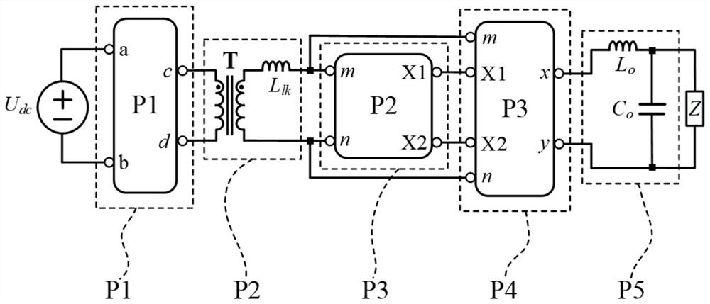
[0037] Such as figure 1 As shown, the active-clamp high-frequency link inverter provided by the present invention includes a primary-side conversion circuit, a high-frequency transformer, an active clamp circuit, a secondary-side conversion circuit, and a low-pass filter. The primary conversion circuit is an inverter circuit, including a full-bridge circuit, a half-bridge circuit, a push-pull circuit, etc., the input is connected to a DC power supply, and the output is connected to the input terminal of a high-frequency transformer.

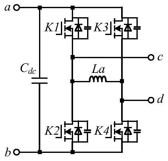
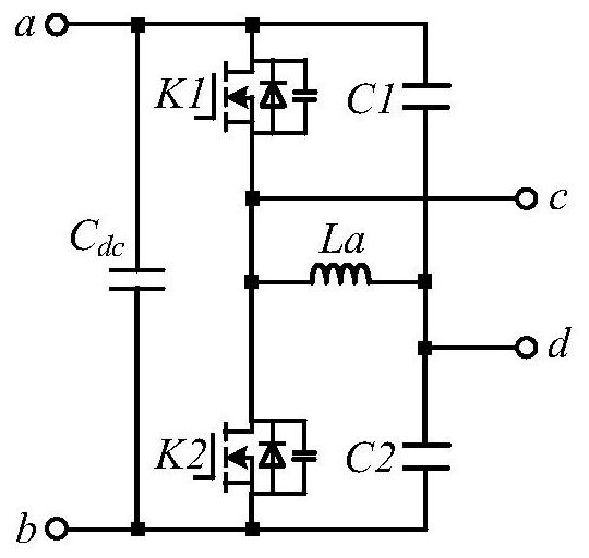
[0038] Such as figure 2 Shown is a full-bridge inverter circuit; image 3 Shown is a half-bridge inverter circuit.

[0039] The active clamping circuit includes an active clamping bridge and a clamping capacitor, and the output side of the active clamping bridge is connected in parallel with the clamping capacitor. The active clamp bridge is a full bridge structure, including four tubes: upper left tube, lower left tube, upper right tube, and...


PUM


Abstract

The invention discloses an active clamping type high-frequency chain inverter which comprises a primary side conversion circuit, a high-frequency transformer, an active clamping circuit, a secondary side conversion circuit and a low-pass filter part. The primary side conversion circuit is a DC/AC inverter circuit; the active clamping circuit comprises an active clamping bridge and a clamping capacitor, losslessly absorbs leakage inductance energy of the high-frequency transformer and feeds back the leakage inductance energy to an input end; the secondary side conversion circuit is a hybrid AC conversion circuit and is composed of a DC/AC half-bridge and an AC/AC half-bridge, and the two half-bridges form a full bridge and output alternating current. According to the invention, single-stage high-frequency isolation inversion from input to output is realized, and no intermediate direct-current bus exists. Under the same working condition, the withstand voltage and output of the device are the same as those of a full-bridge inverter. And through lossless active clamping, the leakage inductance voltage spike problem of the high-frequency transformer is solved. The inverter has the characteristics of high isolation, small size, simplicity in control, good stability, high efficiency and the like.

Description

technical field [0001] The invention relates to power electronic inverter technology, in particular to an active clamp type high-frequency link inverter. Background technique [0002] With the rapid development of power electronics technology, inverters are widely used in production, transportation, aerospace, new energy power generation and other fields. The traditional inverter technology belongs to the low-frequency chain inverter technology. Due to the existence of the low-frequency transformer, it causes problems such as large volume, heavy weight, and high noise. However, the high-frequency transformer used in the high-frequency chain inverter technology has a smaller volume and lighter weight. Features such as lower weight and higher efficiency have gradually attracted attention. [0003] High-frequency chain inverter technology is divided into two types, one is composed of isolated DCDC and DCAC inverter two-stage conversion, with an intermediate DC bus; the other i...

Claims


Application Information

Patent Timeline
Patent Type & Authority Applications(China)
IPC IPC(8): H02M7/5387H02M7/538H02M1/32
CPCH02M7/53871H02M7/53803H02M1/32
Inventor 徐千鸣张家奎郭鹏陈燕东何志兴胡家瑜莫楠王雁罗安
Owner HUNAN UNIV
Why Eureka
Try Eureka