Real-time fault distinguishing circuit and distinguishing method for potentiometer type angle sensor
A technology of rotation angle sensor and real-time fault, which is applied in the direction of measuring resistance/reactance/impedance, instruments, and electrical devices, etc. It can solve the problems of potentiometer brush material aging, wear cost, sensitivity, etc., and achieve high reliability and simple circuit , to achieve easy results
- Summary
- Abstract
- Description
- Claims
- Application Information
AI Technical Summary
Problems solved by technology
Method used
Image
Examples
Embodiment 1
[0044] Such as Figure 5 As shown, the present invention includes a potentiometer VR, a bias resistor Rtest, and a single-chip microcomputer U including an analog-to-digital converter ADC, an IO port with a push-pull output and a high-impedance input.
[0045] The upper end of the potentiometer VR is connected to the positive end X of the reference voltage Vref, the lower end is connected to the reference ground D, and the brush is connected to the positive end of the output voltage Vx; one end of the bias resistor Rtest is connected to the brush end of the potentiometer VR, and the other end is connected to node A ;
[0046] The power supply voltage VCC of the microcontroller U is connected to the positive terminal X of the reference voltage Vref, the input analog quantity Adin is connected to the brush of the potentiometer VR, and the IO port is connected to the node A. The single-chip microcomputer U controls the switch K1 and the switch K2, and the IO port is connected be...
Embodiment 2
[0058] The real-time fault discrimination method of the potentiometer type rotation angle sensor of the present invention comprises the following steps:
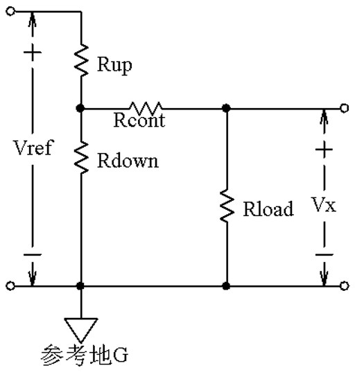
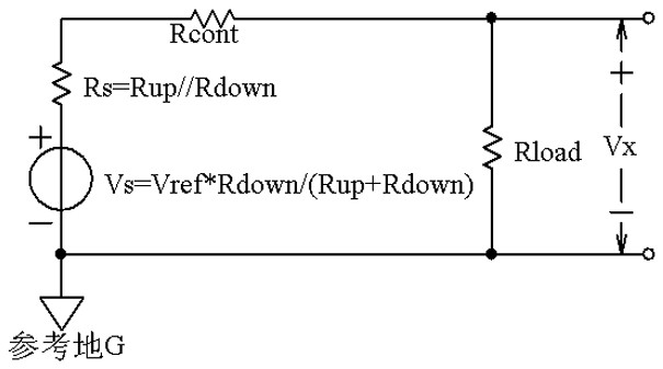
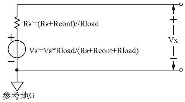
[0059] A, potentiometer type angle sensor real-time fault discrimination method is applied to the potentiometer type angle sensor real-time fault discrimination circuit in embodiment 1, and this circuit diagram is Figure 5 , Figure 4 yes Figure 5 The simplified circuit, Figure 6 yes Figure 4 the equivalent circuit.
[0060] B. Calculate the internal resistance Rs of the potentiometer.
[0061] The switch K1 and switch K2 are controlled by the single-chip microcomputer U, and the output voltage Vx is measured by the analog-to-digital converter ADC inside the single-chip microcomputer to obtain the first output voltage Vx1, and the internal resistance of the potentiometer Rs=Rup*Rdown / (Rup is calculated by the single-chip microcomputer U +Rdown). Since the contact resistance Rcont ranges from about 1Ω to tens of kΩ ...
PUM
 Abstract
Description
Claims
Application Information
 - R&D
- Intellectual Property
- Life Sciences
- Materials
- Tech Scout
- Unparalleled Data Quality
- Higher Quality Content
- 60% Fewer Hallucinations
Browse by: Latest US Patents, China's latest patents, Technical Efficacy Thesaurus, Application Domain, Technology Topic, Popular Technical Reports.
© 2025 PatSnap. All rights reserved.Legal|Privacy policy|Modern Slavery Act Transparency Statement|Sitemap|About US| Contact US: help@patsnap.com


