
Diaphragm valve

A diaphragm valve and diaphragm technology, which is applied in the direction of diaphragm valves, diaphragms, valve devices, etc., can solve the problems of inability to cope with changes in valve seat thickness, inability to cope with high temperature state specifications, thickness changes, etc., to reduce unevenness and prevent valve seat leakage , the effect of reducing the amount of adsorption

Pending Publication Date: 2022-04-01
FUJIKIN INC
View PDF3 Cites 0 Cited by
  • Summary
  • Abstract
  • Description
  • Claims
  • Application Information

AI Technical Summary

Problems solved by technology

[0009] However, in the above-mentioned conventional diaphragm valve in which a fluororesin coating is formed on the entire surface of the metal diaphragm on the valve seat side, the gas in the flow path may leak to the outside of the diaphragm valve.
In addition, as shown in an example of the valve seat described in Patent Document 3, when the valve seat is made of resin, the thickness of the resin valve seat itself is about several millimeters, and when used in a high temperature state, due to thermal expansion, Thickness changes greatly due to creep caused by long-term use
In the case of an actuator that operates the valve body, such as a piezoelectric control valve, the general stroke range is less than 100 μm, and it may not be able to cope with changes in the thickness of the valve seat due to thermal expansion and creep, and may not be able to cope with high temperature conditions. Questions like specifications

Method used


Image

  • Diaphragm valve
  • Diaphragm valve
  • Diaphragm valve

Examples


Embodiment Construction

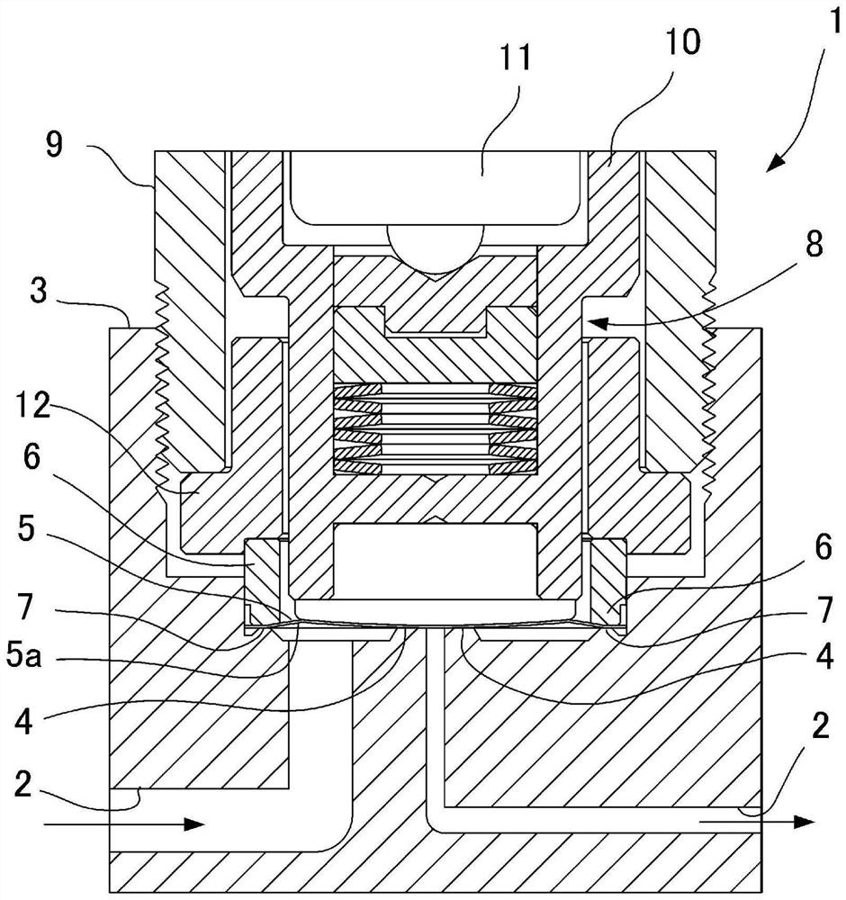
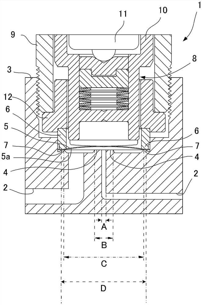
[0038] Regarding an embodiment of the present invention, refer to Figure 1 to Figure 8 while explaining. In addition, in all drawings, the same code|symbol is attached|subjected to the same or similar component.

[0039] refer to figure 1 as well as figure 2 The diaphragm valve 1 includes: a valve body 3 formed with a flow path 2; a valve seat 4 formed on the flow path 2; a metal diaphragm 5 that opens and closes the flow path 2 by contacting or moving away from the valve seat 4; Fixing the metal diaphragm 5 to a pair of clamping portions 6, 7 of the valve body 3 by clamping the peripheral edge portions of both sides of the metal diaphragm 5 respectively; and making the metal diaphragm 5 contact the valve seat 4 or Remote actuator 8.

[0040] The valve body 3 can be formed of metal such as stainless steel, for example. In addition, both the clamping parts 6 and 7 can be formed of metal (including alloy). In the example shown in the drawings, the clamping portion 7 abu...


PUM

PropertyMeasurementUnit
surface roughnessaaaaaaaaaa
diameteraaaaaaaaaa
thicknessaaaaaaaaaa

Abstract

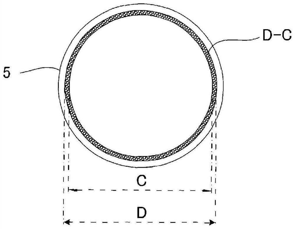
A diaphragm valve is provided with: a valve body (3) in which a flow path (2) is formed; a valve seat (4) formed in the flow path; a metal diaphragm (5) that opens and closes the flow path by coming into contact with or being separated from the valve seat; a pair of clamping parts (6, 7) which respectively clamp the peripheral edge parts of the two side surfaces of the metal diaphragm and fix the metal diaphragm to the valve body; and an actuator (8) for bringing the metal diaphragm into contact with or away from the valve seat, in which a fluororesin coating layer is formed on a valve seat side surface (5a) of the metal diaphragm at least in a contact region (B-A) with the valve seat within a region (C) surrounded by a nip region (D-C) between the valve seat side surface and the nip (7), excluding the nip region (D-C).

Description

technical field [0001] The present invention relates to a diaphragm valve, in particular to a diaphragm valve with a metal diaphragm suitable for flow control of process gas used in semiconductor manufacturing. Background technique [0002] Conventionally, a diaphragm valve provided with a metal diaphragm is known for controlling the flow rate of a process gas for semiconductor manufacturing (Patent Documents 1, 2, etc.). The metal diaphragm of this type of diaphragm valve is formed of an extremely thin metal plate such as a cobalt-based alloy (SPRON), but there is variation in processing accuracy, and repeated contact and separation from the valve seat to open and close the flow path cause damage. , wear, and sometimes seat leakage. In addition, depending on the type of gas that flows, there is also a problem of diaphragm corrosion. [0003] So, for example, if Figure 9 As shown, there is known a diaphragm valve in which corrosion resistance is improved by applying a flu...

Claims


Application Information

Patent Timeline
Patent Type & Authority Applications(China)
IPC IPC(8): F16K7/14
CPCC09D127/18F16K31/007F16K7/14F16K7/17F16K25/005F16K27/0236F16K7/12C09D127/12
Inventor 平田薰永濑正明日高敦志森崎和之井手口圭佑杉本耕祐北野真史西野功二池田信一
Owner FUJIKIN INC
Learn More