Preparation equipment and preparation method of binder asphalt

A technology for binder asphalt and equipment, which is applied to the preparation equipment and field of binder asphalt, can solve problems such as inability to handle and affect the final quality of modified asphalt, and achieve the effect of improving the final quality

Pending Publication Date: 2022-04-05
刘浩
View PDF1 Cites 0 Cited by
  • Summary
  • Abstract
  • Description
  • Claims
  • Application Information

AI Technical Summary

Problems solved by technology

[0003] For example, a Chinese patent with the application number CN201821570744.7 discloses a modified asphalt preparation equipment, including a device body, a base, a heat-conducting pipe, and a stirring tank. The device body includes a shell and an insulation layer, and the shell is sleeved On the outside of the stirring tank, a heat-conducting pipe and an insulation layer for insulating the heat-conducting pipe are arranged between the stirring tank and the shell. The shell is plugged with a heat-conducting liquid outlet pipe and a heat-conducting liquid inlet pipe. The heat-conducting liquid The outlet pipe and the heat-conducting liquid inlet pipe communicate with the heat-conducting pipe through the heat-conducting liquid outlet and the heat-conducting liquid inlet. The feed inlet, the base supports and fixes the device body at its top end. This technical solution has the advantages of reasonable design, simple operation, convenient overall heating of the stirring tank and reduction of adhesion; but this technical solution cannot The froth of modified asphalt is processed, which will affect the final quality of modified asphalt, resulting in the limitation of this scheme

Method used


Image

  • Preparation equipment and preparation method of binder asphalt
  • Preparation equipment and preparation method of binder asphalt
  • Preparation equipment and preparation method of binder asphalt

Examples


Embodiment approach

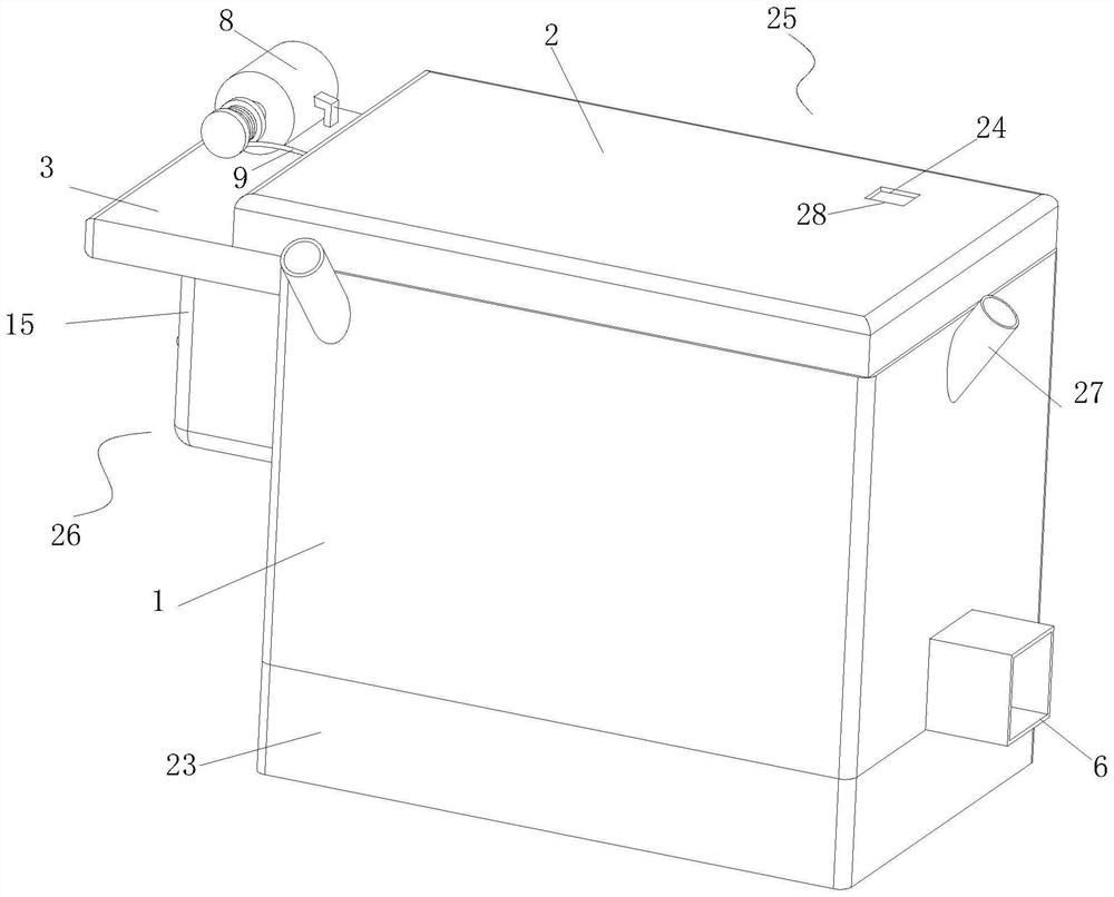
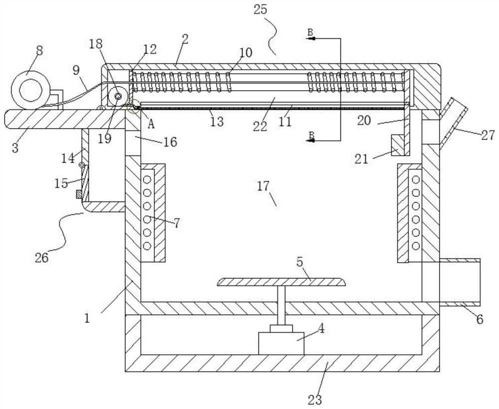
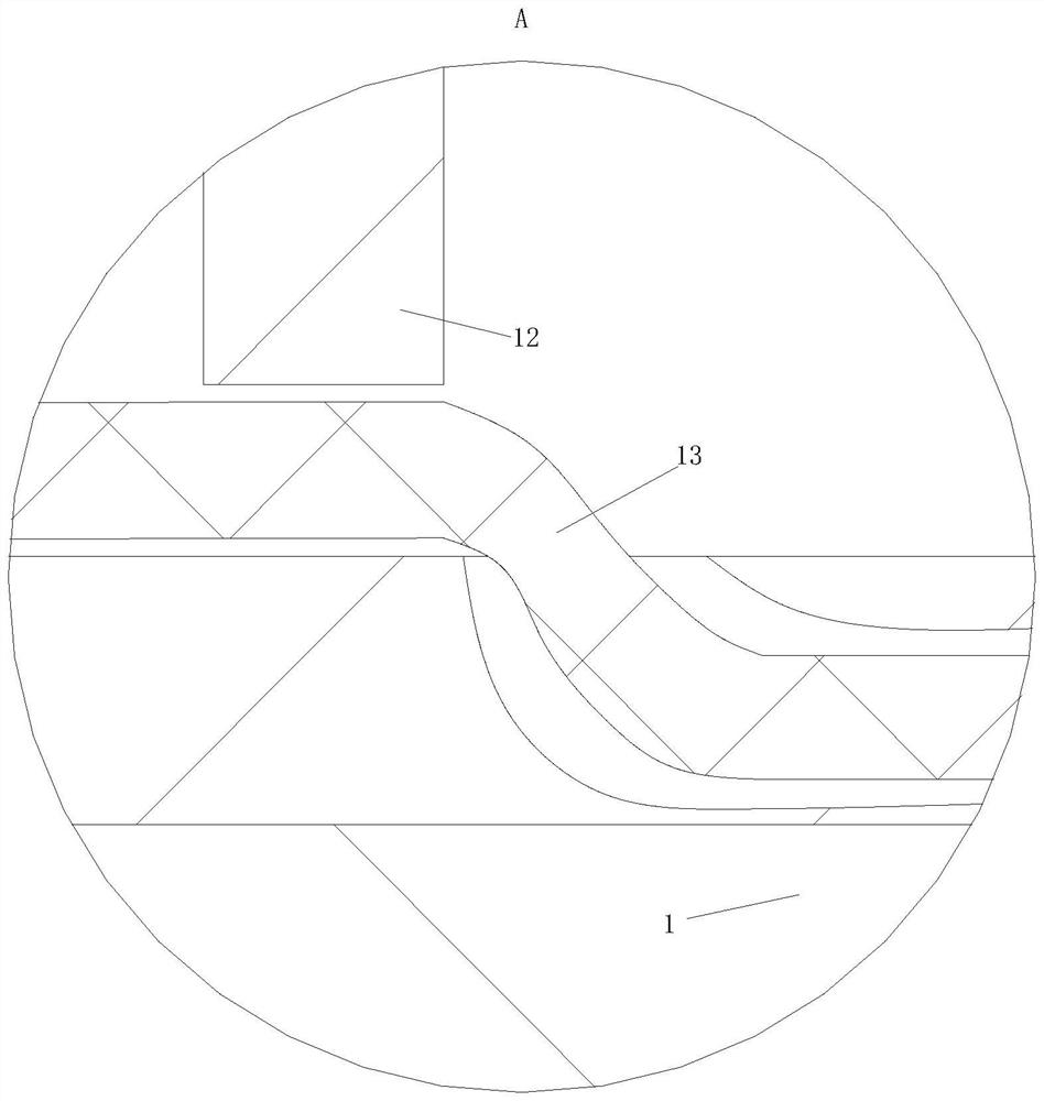
[0043] As an embodiment of the present invention, the defoaming unit 25 includes a motor 8, a traction rope 9, a spring 10, a T-shaped slot 11, a scraper 20 and a baffle 12; the motor 8 is fixedly connected to the fixed plate 3; The output shaft of the motor 8 is fixedly connected and is wound with a traction rope 9; the other end of the traction rope 9 passes through the box cover 2 and the baffle plate 12 and is fixedly connected to the scraper 20; the inside of the box cover 2 is provided with a cavity 22; a baffle plate 12 is provided near the motor 8 in the cavity 22; the baffle plate 12 is fixedly connected with the cavity wall of the cavity 22; the traction rope 9 is set between the scraper 20 and the baffle plate 12 There is a spring 10; the two ends of the spring 10 are fixedly connected with the baffle plate 12 and the scraper 20 respectively; the side of the box cover 2 close to the box body 1 is provided with a T-shaped groove 11; the T-shaped groove 11 is connected...


PUM


Abstract

The invention relates to the technical field of asphalt, in particular to preparation equipment and a preparation method of binder asphalt, and the preparation equipment comprises a box body, a box cover, a fixed plate, an air outlet, a stirrer and a heating resistor; the box body is in a cuboid shape, a fixing plate is fixedly connected to the edge of the side face of the box body, a liquid outlet is formed in the bottom of the box body, and a rectangular groove is formed in the box body. The device further comprises a defoaming unit and a collecting unit; the defoaming unit is used for treating floating foam on the surface of binder asphalt; the collecting unit is used for collecting floating foam of the defoaming unit; a rectangular through hole is formed in the position, close to the collecting unit, of the box body. The defoaming unit is used for scraping floating foam on the surface of the medium-temperature asphalt, and the collecting unit is used for collecting the floating foam on the surface, so that the floating foam on the surface of the medium-temperature asphalt is scraped into the collecting box, the situation that the floating foam enters the medium-temperature asphalt again, and the quality of the finally prepared binder asphalt is affected is reduced, and therefore the device has reasonability and is suitable for popularization and application. The method has a practical application effect.

Description

technical field [0001] The invention relates to the technical field of asphalt, in particular to a preparation equipment and method for binder asphalt. Background technique [0002] The main performance indicators of binder asphalt include softening point, quinoline insoluble matter, toluene insoluble matter, coking value, ash, moisture, sodium ion content and mesophase content. When coke is mixed and kneaded, it needs to be well wetted with aggregate coke on the surface of the coke, and can be immersed into the voids of the coke, that is, good penetration performance. In addition, it needs to have a high carbonization yield, that is, the coking value. The higher the coking value, the higher the carbonization yield of the formed composite material during firing, the higher the bulk density of the material, and the greater the mechanical strength, the lower the resistivity of the material, so that the consumption and The lower the cost, the binder asphalt is usually produced...

Claims


Application Information

Patent Timeline
Patent Type & Authority Applications(China)
IPC IPC(8): B01F35/32B01F27/90B01F27/808C10C3/00B01D19/02B01F101/38
Inventor 刘浩徐帅
Owner 刘浩
Why Eureka
Try Eureka