Quasi-switched capacitor type high-gain DC-DC converter

A DC-DC and switched capacitor technology, which is applied in the direction of adjusting electrical variables, converting DC power input to DC power output, and instruments, can solve problems such as high voltage stress of switching tubes, capacitors, and large input current ripples, and achieve improved Improvement of conversion efficiency, voltage gain, and work efficiency

Pending Publication Date: 2022-04-05
镇江金能电力科技有限公司
View PDF6 Cites 1 Cited by
  • Summary
  • Abstract
  • Description
  • Claims
  • Application Information

AI Technical Summary

Problems solved by technology

In order to further improve the performance of the quasi-switching boost network, the switching inductor unit can be added to the quasi-switching boost converter. This method improves the voltage gain of the circuit. The disadvantage is that the input current ripple is large, and the switching tube and capacitor voltage high stress

Method used


Image

  • Quasi-switched capacitor type high-gain DC-DC converter
  • Quasi-switched capacitor type high-gain DC-DC converter
  • Quasi-switched capacitor type high-gain DC-DC converter

Examples


Embodiment Construction

[0022] The technical scheme of the present invention will be described in further detail below in conjunction with the accompanying drawings and specific embodiments, so that those skilled in the art can better understand the present invention and implement it, but the examples given are not intended to limit the present invention.

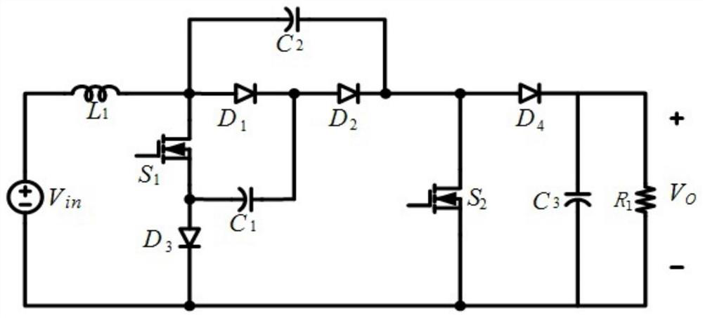
[0023] Such as figure 1 As shown, a quasi-switched capacitor high-gain DC-DC converter includes a first inductor L 1 , the first diode D 1 , the second diode D 2 , the third diode D 3 , the first capacitance C 1 and a second capacitor C 2 , also includes the first MOS tube S 1 , the second MOS tube S 2 , the fourth diode D 4 , the third capacitor C 3 .

[0024] where the first inductance L 1 , the first MOS tube S 1 , the first diode D 1 , the third diode D 3 and the first capacitor C 1 Form a quasi-switching boost unit, the second capacitor C 2 and the second diode D 2 Composing a switched capacitor unit, the second MOS transistor...


PUM


Abstract

The quasi-switched capacitor type high-gain DC-DC converter is characterized in that one end of a first inductor L1 is connected with the positive electrode of a DC input voltage source Vin, and the other end of the first inductor L1 is connected with the negative electrode of a second capacitor C2, the positive electrode of a first diode D1 and the drain electrode of a first MOS tube S1; the source electrode of the first MOS tube S1 is connected with the negative electrode of the first capacitor C1 and the positive electrode of the third capacitor C3, the negative electrode of the first diode D1 is connected with the positive electrode of the second diode D2, and the positive electrode of the first capacitor C1 is connected with the common end of the first diode D1 and the second diode D2. The negative electrode of the second diode D2 is connected with the positive electrode of a second capacitor C2, the drain electrode of a second MOS tube S2 and the positive electrode of a fourth diode D4, the negative electrode of the fourth diode D4 is connected with the positive electrode of a third capacitor C3, and the negative electrode of the third capacitor C3, the source electrode of the second MOS tube S2 and the negative electrode of the third capacitor C3 are all connected with the negative electrode of a direct current input voltage source Vin. Two ends of the third capacitor C3 are used for parallel connection with a load and supplying power to the load.

Description

technical field [0001] The invention relates to a quasi-switch capacitor type high-gain DC-DC converter. Background technique [0002] With the increasingly serious problems of global environmental pollution and energy shortage, the development of renewable energy has been highly valued. Among them, photovoltaic new energy based on solar energy has the advantage of rich development resources and is regarded as one of the most promising renewable energy sources. one. However, the output voltage level of photovoltaic cells is low, and the output voltage of a single photovoltaic panel is usually about 25-40V. For a 220V grid-connected system, a high-gain DC-DC converter (Direct current-Direct current converter) is required to boost the voltage. To meet the voltage level requirements of the DC side of the grid-connected inverter. [0003] The traditional Boost converter has a simple structure and is easy to control, but its boosting capability has great limitations, making it ...

Claims


Application Information

Patent Timeline
Patent Type & Authority Applications(China)
IPC IPC(8): H02M3/158
CPCY02E10/56
Inventor 金涛李海滨
Owner 镇江金能电力科技有限公司
Why Eureka
Try Eureka