MEMS gyroscope

A gyroscope and resonant block technology, applied in the field of gyroscopes, can solve problems such as insufficient drive/detection sensitivity, and achieve the effects of reducing MEMs mechanical noise, improving sensitivity, and improving Coriolis gain.

Pending Publication Date: 2022-04-08
瑞声开泰科技(武汉)有限公司
View PDF0 Cites 0 Cited by
  • Summary
  • Abstract
  • Description
  • Claims
  • Application Information

AI Technical Summary

Problems solved by technology

However, the ring MEMS gyroscope in the related art is still insufficient in driving / detecting sensitivity due to limitations of driving / detecting capacitance and effective vibration mass

Method used


Image

  • MEMS gyroscope
  • MEMS gyroscope
  • MEMS gyroscope

Examples


Embodiment 1

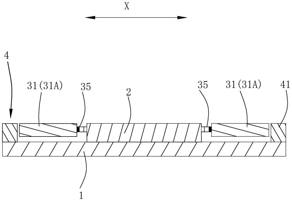
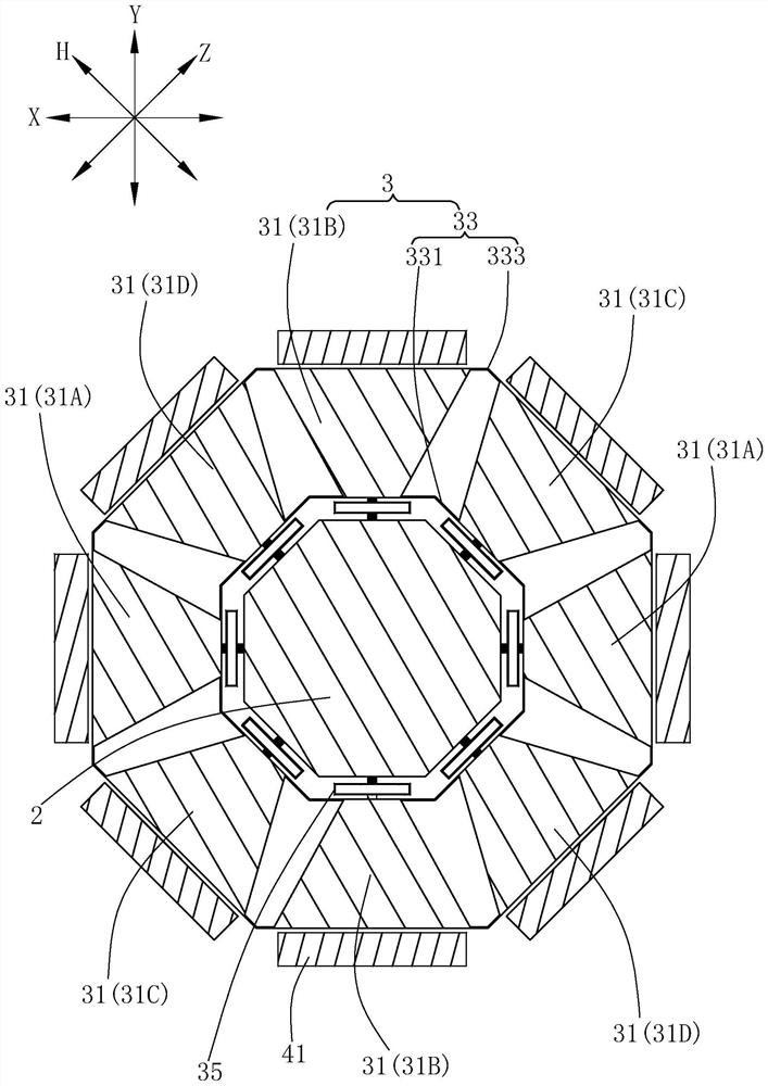
[0034] Please refer to Figure 1 to Figure 3 , the MEMS gyroscope includes a substrate 1 , an anchor point 2 , a resonator 3 and a transducer 4 . The anchor point 2 and the transducer 4 are fixed on the base 1 , and the resonator 3 is suspended on the base 1 .

[0035] Resonator 3 adopts a fully symmetrical design. Specifically, the resonator 3 includes eight resonant blocks 31 distributed in a ring and equally spaced along the circumferential direction of the anchor point 2 , and a coupling beam 33 connecting two adjacent resonant blocks 31 . Among them, the eight resonant blocks 31 are divided into a pair of first resonant blocks 31A arranged at intervals along the first axis X, a pair of second resonant blocks 31B arranged at intervals along the second axis Y, and a pair of second resonant blocks 31B arranged at intervals along the third axis Z. A pair of third resonant blocks 31C and a pair of fourth resonant blocks 31D arranged at intervals along the fourth axis H. Whe...

Embodiment 2

[0049] Please refer to Figure 4 to Figure 5 The difference between the second embodiment and the first embodiment is that the transducer 4 includes 8N internal electrodes 43, and the resonant block 31 is provided with N jacks 311 along the axial direction of the anchor point 2, and the internal electrodes 43 correspond to each other. The internal electrode 43 corresponding to the first resonant block 31A and the internal electrode 43 provided corresponding to the second resonant block 31B have opposite potentials; the internal electrode 43 corresponding to the third resonant block 31C and the corresponding The internal electrodes 43 of the fourth resonant block 31D have opposite potentials; N is a positive integer, and when N is greater than 1, the N sockets 311 on each resonant block 31 are arranged at intervals along the radial direction of the anchor point 2 .

[0050] In this embodiment, the internal electrode 43 includes a first electrode 431 and a second electrode 433 a...


PUM


Abstract

The invention discloses an MEMS (Micro Electro Mechanical System) gyroscope. The MEMS gyroscope comprises an anchor point; the resonator comprises eight resonance blocks arranged at equal intervals and coupling beams connecting every two adjacent resonance blocks, the resonance blocks are connected to the anchor points through anchoring beams, the coupling beams comprise the first coupling beam and the second coupling beam, and the anchoring beams can decouple radial movement and circumferential movement of the resonance blocks; the eight resonance blocks are divided into a pair of first resonance blocks, a pair of second resonance blocks, a pair of third resonance blocks and a pair of fourth resonance blocks; the transducer is coupled with the resonator through an electric field; the working modes comprise a vibration mode and a detection mode, and in the vibration mode, the transducer drives the pair of first resonance blocks to vibrate along a first axis, drives the pair of second resonance blocks to vibrate along a second axis, and drives the pair of third resonance blocks to vibrate along a fourth axis and drives the pair of fourth resonance blocks to vibrate along the third axis; in the detection mode, the transducer is used for detecting the vibration of the pair of third resonance blocks along the third axis and the vibration of the pair of fourth resonance blocks along the fourth axis.

Description

【Technical field】 [0001] The invention relates to the technical field of gyroscopes, in particular to a MEMS gyroscope. 【Background technique】 [0002] MEMS gyroscope is a miniature angular velocity sensor manufactured by micromachining technology and microelectronics technology. Typical structures of MEMS gyroscopes include tuning fork type, ring type, nested ring type, disc, hemispherical gyroscope, etc. Among them, the ring MEMS gyroscope has a highly symmetrical drive and detection mode, which calculates the magnitude of the angular velocity input through the energy of the detection mode. However, the ring MEMS gyroscope in the related art still has insufficient driving / detecting sensitivity due to limitations of driving / detecting capacitance and effective vibration mass. [0003] Therefore, it is necessary to provide a new MEMS gyroscope to solve the above problems. 【Content of invention】 [0004] The object of the present invention is to disclose a MEMS gyroscope....

Claims


Application Information

Patent Timeline
Patent Type & Authority Applications(China)
IPC IPC(8): G01C19/5691B81B7/02
CPCG01C19/5733G01C19/5712G01C19/5684
Inventor 杨珊占瞻严世涛马昭阚枭彭宏韬洪燕黎家健陈秋玉
Owner 瑞声开泰科技(武汉)有限公司
Why Eureka
Try Eureka