Low-disturbance soil treatment device

A low-disturbance, soil technology, used in soil-lifting machinery, plant protection covers, agricultural machinery and implements, etc., can solve problems such as affecting plant growth, achieve uniform electric field distribution, improve treatment effects, and reduce waste.

Active Publication Date: 2022-04-12
中科华鲁土壤修复工程有限公司
View PDF12 Cites 0 Cited by
  • Summary
  • Abstract
  • Description
  • Claims
  • Application Information

AI Technical Summary

Problems solved by technology

[0002] The surface layer of the polluted soil is in contact with the pollutants before the pollutants, and the soil pollution gradually weakens from top to bottom. When the existing high-temperature air removes volatile organic compounds in the soil, the layers of the soil are often disturbed and crushed, resulting in residual metal pollutants. Spread to each soil layer, and the plant root system is mostly in the middle and lower layers of the mellow soil layer, affecting plant growth

Method used


Image

  • Low-disturbance soil treatment device
  • Low-disturbance soil treatment device
  • Low-disturbance soil treatment device

Examples


Embodiment 1

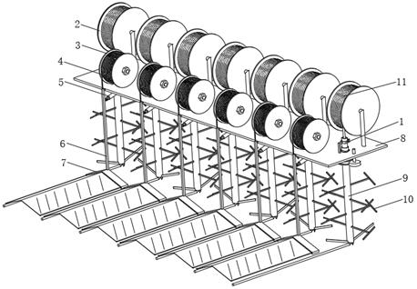
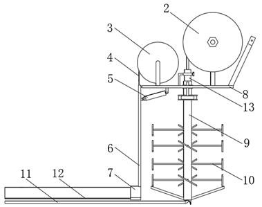
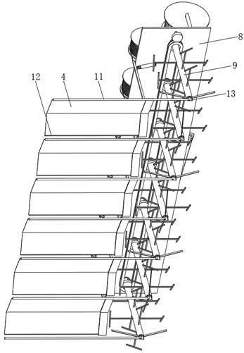
[0031] Example 1: Please refer to figure 1 , figure 2 , image 3 , Figure 4 and Figure 7 , this embodiment discloses a low-disturbance soil treatment device, including a support base 8, on which several crushing components are installed along the length direction of the support base 8, the working state of the low-disturbance soil treatment device is along the width direction of the support base 8 Move, the crushing assembly includes a circular insertion tube 13, a drive tube 9 mounted on the support base 8 and rotatable vertically, and a rotatable first storage tray 2 installed on the support base 8, and on the support base 8 A mounting hole is opened, and the inner wall of the mounting hole is connected to the outer upper part of the drive tube 9 through bearing rotation. The blind tube 11 is wound and accommodated on the first storage tray 2, and the insertion tube 13 is inserted into the drive tube 9 and inserted into the tube. Both ends of 13 protrude from the driv...

Embodiment 2

[0050] Embodiment two: if Figure 4 As shown, this embodiment discloses a low-disturbance soil treatment device, its structure is roughly the same as that of Embodiment 1, the difference is that the soil dividing plate 7 described in this embodiment includes an upper pinch plate 71, a lower pinch plate 72. The upper buckle plate 71 and the lower buckle plate 72 are connected together by buckles or bolts. The lower buckle plate 72 is provided with a receiving groove 74, and the receiving groove 74 is open at one end away from the forward direction.

[0051] Both ends of the width of the covering film 4 are provided with soft clamping strips 12 .

[0052] Both sides of the receiving groove 74 in the length direction are provided with long grooves 73 , and the two long grooves 73 gradually approach the lower end of the conduit 6 from far to near, and the long grooves 73 are adapted to the clamping strip 12 .

[0053] The working process and principle of this embodiment are:

[...

Embodiment 3

[0055] Embodiment three: as Figure 4 As shown, this embodiment discloses a low-disturbance soil treatment device, its structure is roughly the same as that of Embodiment 1, the difference is that this embodiment also includes a conductive plate 20 and a voltage regulating assembly 21, and the dead pipe 11 A wire 22 is provided, the negative terminal of the voltage regulation assembly 21 is electrically connected to the conductive plate 20, the positive terminal of the voltage regulation assembly 21 is electrically connected to the wire 22, and the voltage regulation assembly 21 is powered by the grid or vehicle power generation.

[0056] The voltage regulating component 21 is a common DC output voltage regulating device in the prior art, and its structure and internal circuit are common knowledge, and will not be repeated here.

[0057] Preferably, the wire 22 can slide in the dead leg 11 .

[0058] The working process and principle of this embodiment are:

[0059] Pour wat...


PUM


Abstract

The invention discloses a low-disturbance soil treatment device which comprises a supporting seat, a plurality of smashing assemblies are installed on the supporting seat in the length direction of the supporting seat, and each smashing assembly comprises an insertion pipe, a driving pipe installed on the supporting seat and capable of rotating and a first storage disc installed on the supporting seat and capable of rotating. A blind pipe is wound on the first storage disc, the insertion pipe is inserted into the driving pipe, the two ends of the insertion pipe extend out of the driving pipe, the supporting seat supports the insertion pipe through a support, one end of the blind pipe penetrates in from the upper end of the insertion pipe and penetrates out from the lower end of the insertion pipe, and a film covering assembly is arranged between every two adjacent smashing assemblies. According to the low-disturbance soil treatment device, low-disturbance removal of volatile organic matters and metal pollutants is achieved, diffusion of residual pollutants is reduced, and restoration and improvement of soil can be accelerated.

Description

technical field [0001] The invention relates to the technical field of soil treatment, in particular to a low-disturbance soil treatment device. Background technique [0002] The surface layer of the polluted soil is in contact with the pollutants before the pollutants, and the soil pollution gradually weakens from top to bottom. When the existing high-temperature air removes volatile organic compounds in the soil, the layers of the soil are often disturbed and crushed, resulting in residual metal pollutants. It spreads to each soil layer, and the plant root system is mostly in the middle and lower layers of the mellow soil layer, which affects plant growth. Contents of the invention [0003] The technical problem to be solved by the present invention is to overcome the existing defects and provide a low-disturbance soil treatment device, which realizes the low-disturbance removal of volatile organic compounds and metal pollutants, reduces the diffusion of residual polluta...

Claims


Application Information

Patent Timeline
Patent Type & Authority Applications(China)
IPC IPC(8): A01B77/00A01G13/02
Inventor 孙博程木峰李永辉贾富舜战礼宁
Owner 中科华鲁土壤修复工程有限公司
Why Eureka
Try Eureka