
Rice huller

The technology of a grain hulling machine and a machine body is applied in the field of grain hulling machines, which can solve the problems of low production efficiency, high inclusion rate of rice husks, rough grains and incomplete separation and discharge of rice husks, etc., and achieves the effect of improving the efficiency of grain husking.

Active Publication Date: 2022-04-12
重庆灏真现代农业有限公司
View PDF20 Cites 2 Cited by
  • Summary
  • Abstract
  • Description
  • Claims
  • Application Information

AI Technical Summary

Problems solved by technology

[0002] Rice processing includes steps such as raw material cleaning, husking, separation of paddy and rough mixture, among which husking refers to a process of removing chaff from rice, which is generally processed by a husker. When the existing huskers are used for rice processing, The separation and discharge of rice husk and rice husk is not complete, and the inclusion rate of rice husk in the rice husk collection cylinder is high, which requires repeated screening, resulting in low production efficiency

Method used


Image

  • Rice huller
  • Rice huller

Examples


Embodiment 1

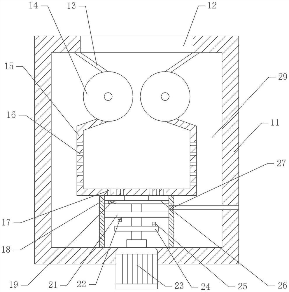
[0038] A rice huller, such as attached figure 1 As shown, it includes a frame and a body 11 fixed on the frame by bolts, and an opening 12 is arranged on the upper part of the body 11 .

[0039] Several driving parts are fixed on the body 11. In this embodiment, the driving parts are single-phase motors 23 and there are two single-phase motors 23 (not shown in the figure). The output shafts of the single-phase motors 23 are coaxially fixed with a The rubber roller 14 below 12 forms a gap between adjacent rubber rollers 14, and several scrapers 13 are arranged on the body 11. One end of the scraper 13 is fixed on the body 11, and the other end of the scraper 13 is against the rubber roller 14. The scrapers 13 are inclined and two adjacent scrapers 13 are arranged in a conical shape.

[0040] A separation cylinder 15 is arranged in the body 11, and a cavity 29 is formed between the separation cylinder 15 and the body 11. The cavity 29 is communicated with a negative pressure tu...

Embodiment 2

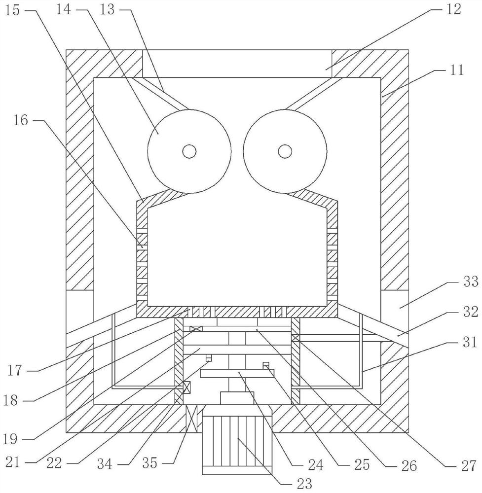
[0047] The difference between embodiment two and embodiment one is that, as attached figure 2 As shown, the screw on the support cylinder 18 is fixed with the second air outlet check valve 34 located below the second partition 21, the second air outlet check valve 34 is connected with the air pipe 31, and the air outlet end of the air pipe 31 faces the upper part of the body 11. 11 is fixed with a second air intake one-way valve 35 located below the second partition 21 , and the second air intake one-way valve 35 communicates with the support cylinder 18 .

[0048] The side wall of the body 11 is provided with some discharge openings 33, and the screws in the discharge openings 33 are fixed with an inclined drain plate 32, the drain plate 32 is arranged in a ring, and one side of the drain plate 32 is rotatably matched with the separation cylinder 15, and the drain plate There are several passages on the 32, and the width of the passages decreases successively from top to bot...


PUM


Abstract

The invention belongs to the technical field of rice processing equipment, and provides a rice huller which comprises a machine body with an opening in the upper portion and a plurality of driving parts arranged on the machine body, rubber rollers located below the opening are coaxially fixed to output shafts of the driving parts, and a gap is reserved between every two adjacent rubber rollers; a separation barrel located below the gap is arranged in the machine body, the upper portion of the separation barrel abuts against the rubber roller, a plurality of first separation holes are formed in the side wall of the separation barrel, a power piece is fixed to the machine body, and an output shaft of the power piece is fixedly connected with the separation barrel; a supporting cylinder located outside the power part is arranged on the lower portion of the separation cylinder and is in running fit with the separation cylinder, and a plurality of second separation holes communicating with the supporting cylinder are formed in the bottom of the separation cylinder. The rice processing device is simple in structure, rice is processed and produced, rice hulls in the rice processing process are removed, and the rice processing efficiency is improved.

Description

technical field [0001] The invention belongs to the technical field of rice processing equipment, and in particular relates to a rice huller. Background technique [0002] Rice processing includes steps such as raw material cleaning, husking, and separation of paddy and rough mixture. Husking refers to a process of removing chaff from rice, which is generally processed by a husker. When the existing huskers are used for rice processing, The separation and discharge of rice husk and rice husk is not complete, and the inclusion rate of rice husk in the rice husk collection cylinder is high, which requires repeated screening, resulting in low production efficiency. Contents of the invention [0003] The invention aims to solve the technical problems existing in the prior art, and provides a rice husker to improve the efficiency of rice husking. [0004] In order to achieve the above object, the present invention adopts the following technical solutions: a rice huller, compri...

Claims


Application Information

Patent Timeline
Patent Type & Authority Applications(China)
IPC IPC(8): B02B3/04B02B7/02B02B7/00B08B15/04B07B1/22B07B1/42B07B1/46B07B7/01B07B11/00B08B1/02B08B1/00
CPCY02P60/14
Inventor 李键
Owner 重庆灏真现代农业有限公司
Learn More