Polarizer protective film or release film edging separation method

A separation method and polarizer technology, which are applied in the direction of machine tools, grinders, and grinding drive devices suitable for grinding the edge of workpieces, can solve problems such as failure to meet customer needs and different bonding forces, and achieve suitable processing temperatures and increased Friction, effect of improving chip removal effect

Pending Publication Date: 2022-04-12
惠州市富丽电子有限公司
View PDF7 Cites 0 Cited by
  • Summary
  • Abstract
  • Description
  • Claims
  • Application Information

AI Technical Summary

Problems solved by technology

[0003] Due to the difference in adhesion between different types of protective films and release films, the adhesion of protective films and release films to polarizers is different. During use, customers need to tear off the protective film and release film. Different types of protective films Different from the peeling force between the release film and the polarizer body, the customer machine has regulations on the initial peeling force of the product. In the current polarizer edging process, when the milling cutter is used for grinding, the peripheral end protective film or the release film and the The polarizer body will not be separated, which makes this type of product unable to meet customer needs

Method used


Image

  • Polarizer protective film or release film edging separation method
  • Polarizer protective film or release film edging separation method
  • Polarizer protective film or release film edging separation method

Examples


Embodiment 1

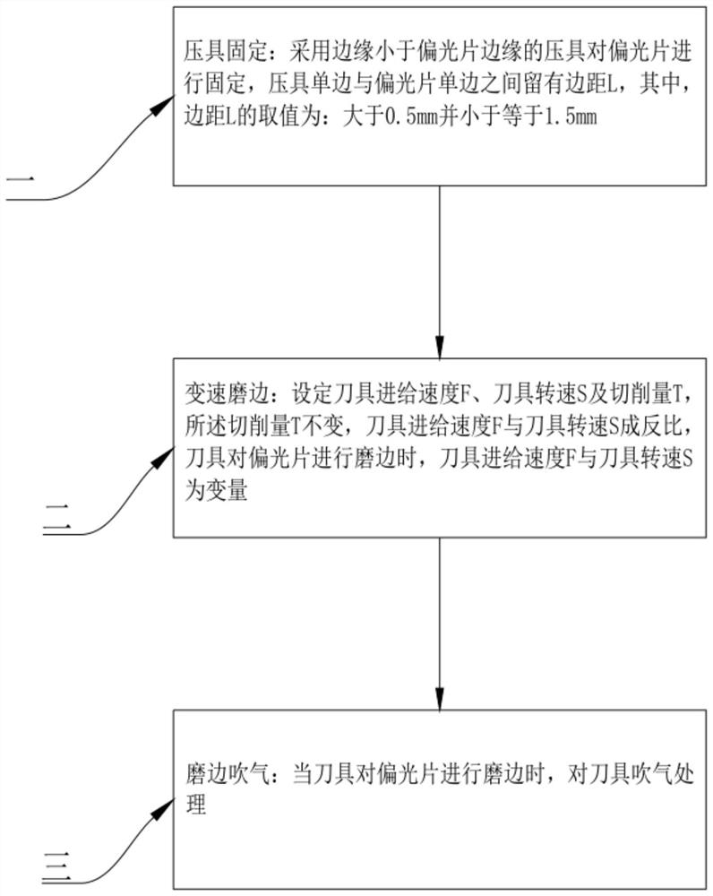
[0023] Such as Figure 1-Figure 3 as shown, figure 1 A flow chart of the method for edging and separating polarizer protective film or release film;

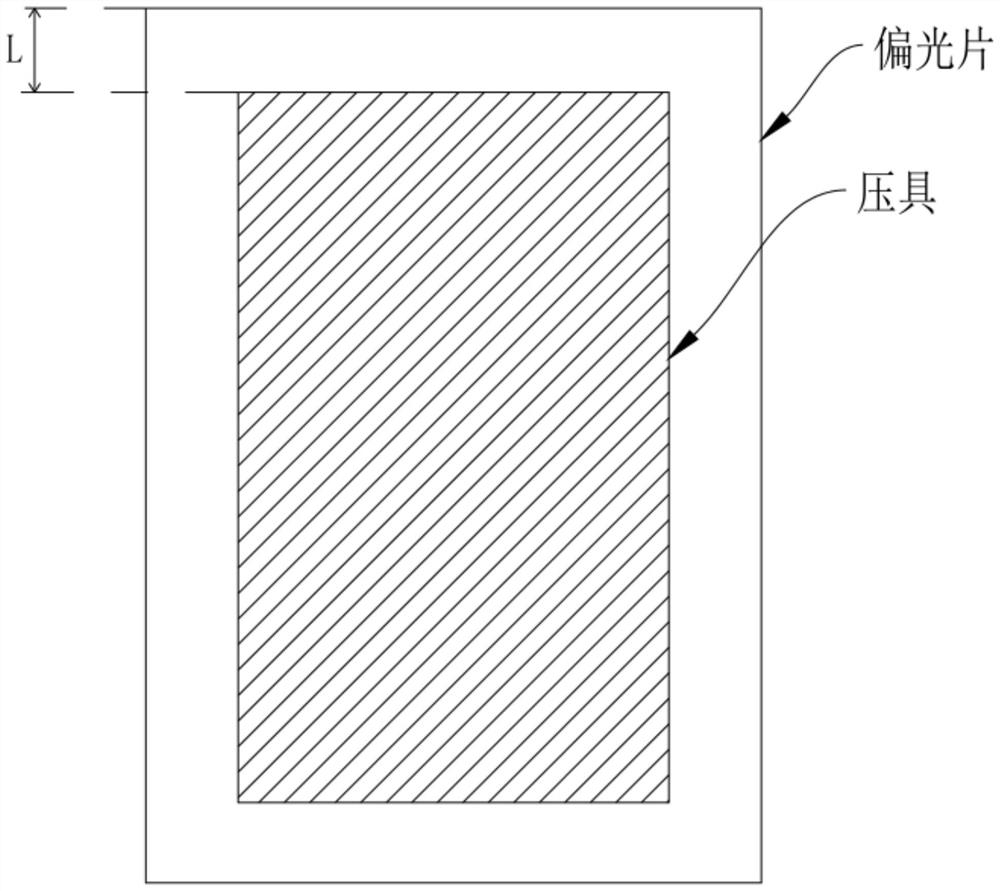
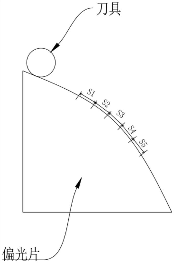
[0024] figure 2 It is a schematic diagram of the position of the presser and the polarizer; image 3 It is a schematic diagram of the edging process of the cutter and the polarizer. The method for edging and separating polarizer protective film or release film of the present application includes:

[0025] (1): Fixing of the press tool: Use the press tool to fix the polarizer to be processed. At the same time, the surface area of ​​the side of the press tool in contact with the polarizer is smaller than the surface area of ​​the polarizer. In other words, after the press tool contacts the polarizer, the pressure There is a margin L between the single side of the tool and the single side of the polarizer, and the value of the margin L is between 0.5 mm and 1.5 mm. In a specific application, the value of the edge distance L i...

Embodiment 2

[0029] Such as Figure 1-Figure 3 as shown, figure 1 A flow chart of the method for edging and separating the polarizer protective film or the release film;

[0030] figure 2 It is a schematic diagram of the position of the presser and the polarizer; image 3 It is a schematic diagram of the edging process of the cutter and the polarizer. The method for edging and separating polarizer protective film or release film of the present application includes:

[0031] (1): Fixing of the press tool: Use the press tool to fix the polarizer to be processed. At the same time, the surface area of ​​the side of the press tool in contact with the polarizer is smaller than the surface area of ​​the polarizer. In other words, after the press tool contacts the polarizer, the pressure There is a margin L between the single side of the tool and the single side of the polarizer, and the value of the margin L is between 0.5mm and 1.5mm. In a specific application, the value of the margin L is...

Embodiment 3

[0035] Such as Figure 1-Figure 3 as shown, figure 1 A flow chart of the method for edging and separating polarizer protective film or release film;

[0036] figure 2 It is a schematic diagram of the position of the presser and the polarizer; image 3 It is a schematic diagram of the edging process of the cutter and the polarizer. The method for edging and separating polarizer protective film or release film of the present application includes:

[0037] (1): Fixing of the press tool: Use the press tool to fix the polarizer to be processed. At the same time, the surface area of ​​the side of the press tool in contact with the polarizer is smaller than the surface area of ​​the polarizer. In other words, after the press tool contacts the polarizer, the pressure There is a margin L between the single side of the tool and the single side of the polarizer, and the value of the margin L is between 0.5 mm and 1.5 mm. In a specific application, the value of the edge distance L i...


PUM


Abstract

The invention discloses an edging separation method for a protective film or a release film of a polaroid. The edging separation method comprises the following steps: (1) an edge distance L is reserved between a single side of a hold-down clamp and a single side of the polaroid; and (2) the cutting amount T is not changed, the cutter feeding speed F is inversely proportional to the cutter rotating speed S, and when the edge of the polaroid is ground by the cutter, the cutter feeding speed F and the cutter rotating speed S are variables. And (3) the cutter is subjected to air blowing treatment. The edge pressing area of the pressing tool on the to-be-machined edge of the polaroid is reduced, the to-be-machined edge has a micro-motion space during edge grinding, and the upper stress and the lower stress are the same and uniform, so that the polaroid protective film separation effect is achieved; the friction force between the cutter and the polaroid is increased, and the cutting stress of the polaroid is changed, so that the protective film is separated from the polaroid; and blowing treatment is conducted on the tool, it is effectively guaranteed that the machining temperature of the tool is appropriate, and the chip removal effect is improved. Through cooperation of several components, separation of the protective film and the polaroid becomes controllable, and the size requirement of a client is met conveniently.

Description

technical field [0001] The invention relates to the technical field of polarizer processing, in particular to a method for edge grinding and separation of a polarizer protective film or a release film. Background technique [0002] The full name of the polarizer is a polarizer. The imaging of a liquid crystal display must rely on polarized light. All liquid crystals have two front and rear polarizers that are attached to the liquid crystal glass to form a liquid crystal sheet with a total thickness of about 1mm. The reason why the polarizer is called Polarizer, the basic structure of polarizer includes: the middle PVA (polyvinyl alcohol), two layers of TAC (triacetyl cellulose), PSA film (pressure sensitive adhesive), Release film (release film) and Protective film (protection film) membrane). Among them, the PVA layer plays a polarizing role, but PVA is very easy to hydrolyze. In order to protect the physical properties of the polarizing film, a layer with high light trans...

Claims


Application Information

Patent Timeline
IPC IPC(8): B24B9/14B24B41/06B24B47/20B24B49/00B24B55/06
CPCY02W30/62
Inventor 雷超张志文凌霄城赵建俏牛学东张利娣
Owner 惠州市富丽电子有限公司
Why Eureka
Try Eureka