Sapphire multi-wire cutting device
A multi-wire cutting, sapphire technology, applied in fine working devices, stone processing equipment, working accessories, etc., can solve problems such as low precision and cutting line interference, and achieve the effect of improving cutting precision and tangent efficiency.
- Summary
- Abstract
- Description
- Claims
- Application Information
AI Technical Summary
Problems solved by technology
Method used
Image
Examples
Embodiment 1
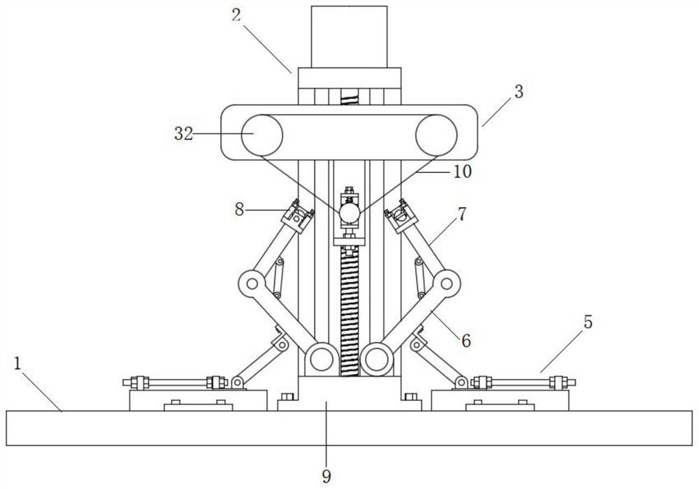
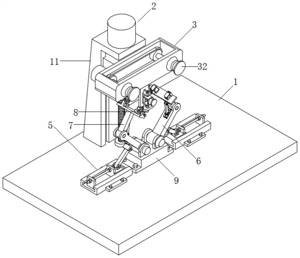
[0043] Such as Figure 1-2 As shown, the present invention provides a sapphire multi-wire cutting device, including a base 1, a cutting wire mechanism 3 and a lifting drive mechanism 2; a fixed beam 11 is welded on the base 1, and the fixed beam 11 is fixedly connected to drive the cutting wire mechanism 3. The lifting drive mechanism 2 for lifting; the base 1 is fixedly connected with a connecting seat 9, and a pair of swing arms 6 arranged in a "V" shape are symmetrically fixedly connected to the connecting seat 9. The angle of the swing arm 6 is fixed, and one end of the swing arm 6 is fixedly connected. There is a rotating arm 7, the end of the rotating arm 7 faces the cutting line 4, and the end of the rotating arm 7 is fixedly connected with a clamping mechanism 8 for fixing the sapphire.
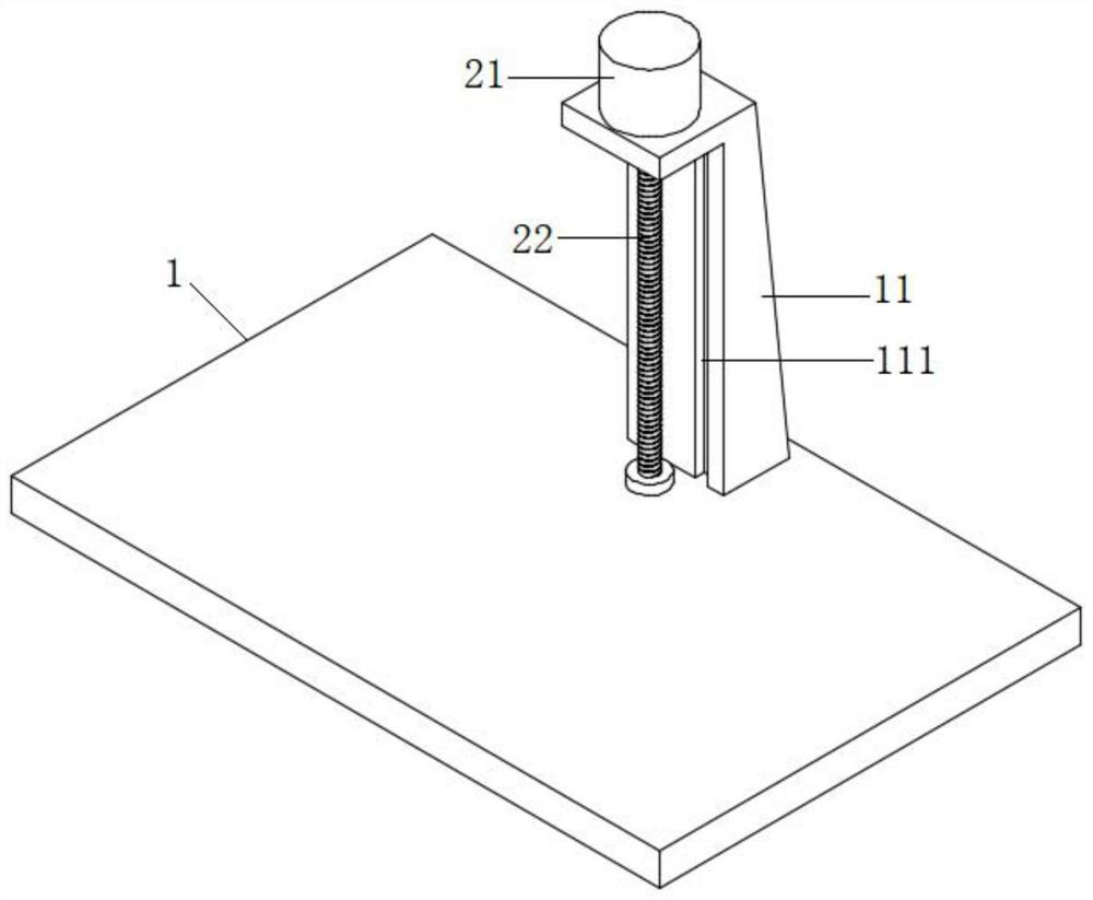
[0044] Such as image 3 As shown, the lifting drive mechanism 2 includes a servo motor 21, the servo motor 21 is fixed on the upper end of the fixed beam 11 by bolts, and the servo mot...
Embodiment 2
[0049] Embodiment 2, based on the above implementation 1, the difference is that
[0050] Such as Figure 8-9 As shown, in order to make the angle of the sapphire relative to the cutting line adjustable, the rotating arm 7 and the swinging arm 6 are connected by a rotating amount, and the end of the connecting arm 6 and the rotating arm 7 is provided with a groove 62, and the inside of the groove 62 Slidingly connected with a slider 63, the inner wall of the groove 62 is provided with a limit slideway; the groove 62 is rotatably connected with an adjusting bolt 64, the adjusting bolt 64 is threaded with the slider 63, and the lower end of the adjusting bolt 64 is rotatably connected to the bottom of the groove 62, And the slide block 63 is rotatably connected with a connecting rod 65, and one end of the connecting rod 65 is rotatably connected to the rotating arm 7. Turning the adjusting bolt 64 can drive the sliding block 63 to slide up and down, thereby driving the rotating ...
Embodiment 3
[0051] Embodiment 3, based on the above implementation 1 or embodiment 2, the difference is that
[0052] In order to adjust the angle of the swing arm 6 and adjust the position and height of the sapphire, the swing arm 6 is connected to the connecting seat 9 in a rotating manner, and the base 1 is fixedly connected with a fixing mechanism 5 for fixing the swing arm 6 , the fixing mechanism 5 includes a fixed seat 51 fixedly connected with the base 1, and both sides of the fixed seat 51 are fixedly connected with a mounting plate 56, the mounting plate 56 is provided with a mounting hole, the mounting plate 56 is fixedly connected with the base 1 through bolts, and the mounting plate 56 is fixedly connected with the base 1. Slider 52 is connected with sliding seat 52 in 51, and fixed seat 51 is provided with limit chute relative to inner surface, makes slide seat 52 slide stably in fixed seat 51, is hinged with support bar 57 on slide seat 52, and support bar 57 one end and swi...
PUM
 Abstract
Description
Claims
Application Information
 - R&D
- Intellectual Property
- Life Sciences
- Materials
- Tech Scout
- Unparalleled Data Quality
- Higher Quality Content
- 60% Fewer Hallucinations
Browse by: Latest US Patents, China's latest patents, Technical Efficacy Thesaurus, Application Domain, Technology Topic, Popular Technical Reports.
© 2025 PatSnap. All rights reserved.Legal|Privacy policy|Modern Slavery Act Transparency Statement|Sitemap|About US| Contact US: help@patsnap.com


