Feeding and proportion control equipment for scale inhibitor and adhesive of sintered carbon rod
A technology of proportional control and scale inhibitor, which is used in manufacturing tools, presses for material molding, mixers with rotary stirring devices, etc. , The effect of preventing the accumulation of residual materials
- Summary
- Abstract
- Description
- Claims
- Application Information
AI Technical Summary
Problems solved by technology
Method used
Image
Examples
Embodiment 1
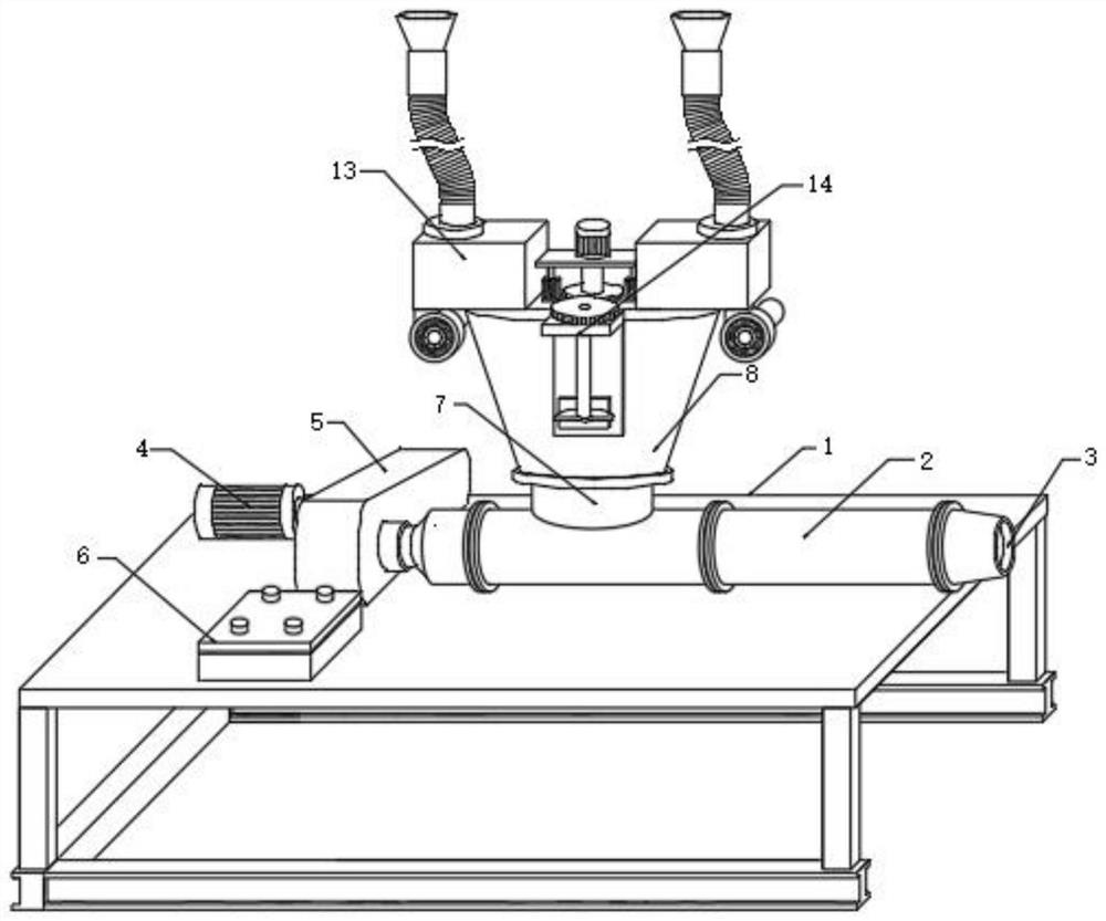
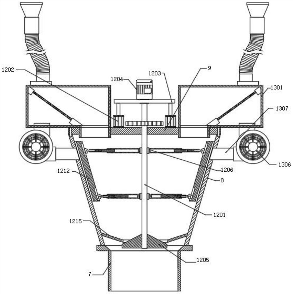
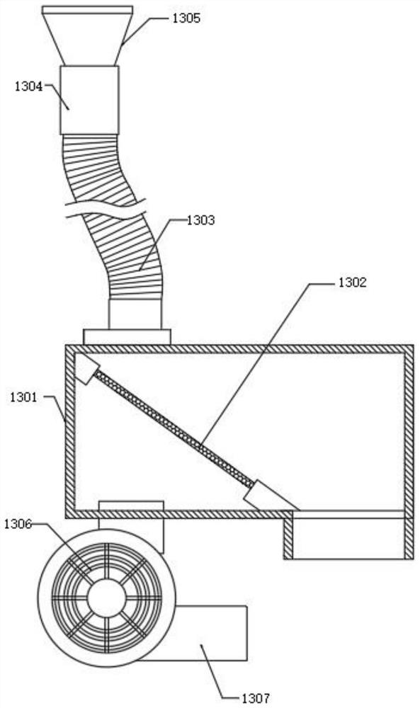
[0028] see Figure 1-7, in the embodiment of the present invention, a kind of antiscalant of sintered carbon rod and adhesion agent feeding and proportion control equipment, comprise: workbench 1; 2 is equipped with a molding port 3 on one side, and a drive motor 4 is fixed on one side of the upper end of the workbench 1. The output end of the drive motor 4 is fixed with a reducer 5 fixed to the upper end of the workbench 1. The output end of the reducer 5 is connected to the extruder. The extrusion molding cylinder 2 is connected to each other to drive the extrusion molding cylinder 2 to operate. The upper end of the workbench 1 is fixed with the control module 6; A hopper 8, a cover plate 9 is fixed on the upper end of the hopper 8; a material mixing assembly 12 arranged in the cover plate 9; Box 1301, the inner cavity of the material box 1301 is provided with a screen 1302, the upper end of the material box 1301 is fixed with a spring tube 1303, the input end of the spring...
Embodiment 2
[0030] see Figure 6-Figure 7 The difference from Embodiment 1 is that in the embodiment of the present invention, the mixing assembly 12 includes: a transmission rod 1201 that penetrates through the cover plate 9, and two hydraulic rods 1202 are fixed on the upper end of the cover plate 9, and the hydraulic rod 1202 A mounting plate 1203 is fixed on the upper end, and a motor 1204 is fixed on the upper surface of the mounting plate 1203; an annular baffle plate 1215 is fixed on the inner cavity of the hopper 8, and the lower end surface of the annular baffle plate 1215 is movably connected with a tapered stopper fixed to the lower end of the transmission rod 1201 1205; and four bearings 1206 symmetrically fixed on both sides of the transmission rod 1201, the rotating end of the bearing 1206 is fixed with a telescopic outer rod 1207, the inner cavity thread of the telescopic outer rod 1207 is engaged with a threaded rod 1208, and the extension end of the threaded rod 1208 is so...
Embodiment 3
[0032] see Figure 7 The difference from Embodiment 1 is that the vibration assembly 14 includes: an L-shaped support plate 1401 fixed on one side of the cover plate 9, the upper end of the L-shaped support plate 1401 rotates through a bearing through a rotating rod 1402, and the upper end of the rotating rod 1402 is fixed with a The driven wheel 1403, the driving wheel 1404 meshing with the driven wheel 1403 is fixed on the surface of the transmission rod 1201, the semi-disc 1405 is fixed at the lower end of the rotating rod 1402; 1406 is fixed with a force plate 1407 near the end of the half disc 1405, and a second spring 1408 is fixed between the force plate 1407 and the L-shaped support plate 1401. The impact plate 1406 is arranged opposite to the hopper 8, and is used for impacting the hopper 8 to cause shaking. When the transmission rod 1201 rotates, it can drive the impact plate 1406 to repeatedly collide with the surface of the hopper 8, vibrating and shaking the resid...
PUM
 Abstract
Description
Claims
Application Information
 - R&D
- Intellectual Property
- Life Sciences
- Materials
- Tech Scout
- Unparalleled Data Quality
- Higher Quality Content
- 60% Fewer Hallucinations
Browse by: Latest US Patents, China's latest patents, Technical Efficacy Thesaurus, Application Domain, Technology Topic, Popular Technical Reports.
© 2025 PatSnap. All rights reserved.Legal|Privacy policy|Modern Slavery Act Transparency Statement|Sitemap|About US| Contact US: help@patsnap.com


