New energy automobile heat dissipation method

A new energy vehicle and cooling device technology, applied in electric vehicles, vehicle energy storage, vehicle components, etc., can solve the problems of affecting battery heat, difficult to cool down, overheating, etc., to extend the flow time, ensure unity, and avoid backflow phenomenon Effect

Pending Publication Date: 2022-04-12
潘馨蕊
View PDF0 Cites 0 Cited by
  • Summary
  • Abstract
  • Description
  • Claims
  • Application Information

AI Technical Summary

Problems solved by technology

[0005] Aiming at the deficiencies of the prior art, the present invention provides a new energy vehicle heat dissipation method, which solves the problem that most of the existing new energy vehicle heat dissipation equipment is used for the heat dissipation of the battery of the new energy vehicle, but the temperature of the ground will continue during use in summer. The heat of the battery is permanently affected, and most of the vehicles are closed, it is difficult to quickly cool down inside, and it is easy to cause damage due to overheating

Method used


Image

  • New energy automobile heat dissipation method
  • New energy automobile heat dissipation method
  • New energy automobile heat dissipation method

Examples


Embodiment 1

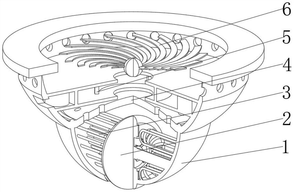
[0041] see Figure 1-5 , the present invention provides a technical solution: a new energy vehicle cooling device, specifically comprising:

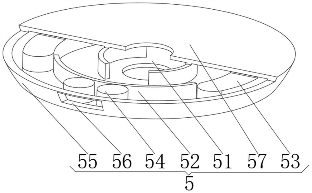
[0042] Protective bottom pocket 1, the protective bottom pocket 1 has a spherical pocket body, and a contact guide wheel 2 installed in the middle of the inner cavity of the spherical pocket, and is installed on the inner surface of the spherical pocket and is located on both sides of the contact guide wheel 2. The coil 3, and the guide device 4 installed on the top of the spherical pocket, and the cooling device 5 installed on the top of the guide device 4, and the fixing device 6 installed on the top of the cooling device 5 pass through the spherical pocket of the protective bottom pocket 1 The design reduces the contact area with the ground during use, reduces the friction of the equipment, and avoids the impact of the equipment on the driving speed during the driving of new energy vehicles. At the same time, the protective bottom poc...

Embodiment 2

[0053] see Figure 1-5 On the basis of Embodiment 1, the present invention provides a technical solution: a new energy vehicle heat dissipation method, comprising the following steps,

[0054] Step 1: install the whole device on the bottom of the new energy vehicle through the fixing ring plate 61 in the fixing device 6;

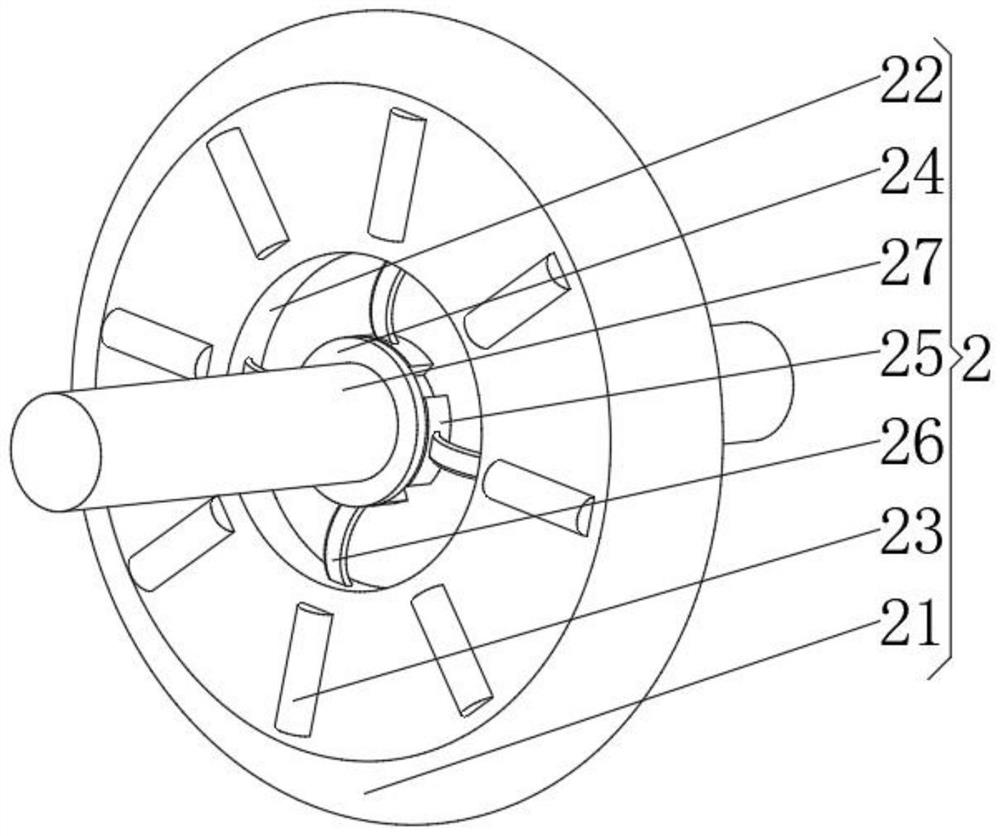
[0055] Step 2: When the new energy vehicle is running, the contact wheel 21 sinks under its own weight and contacts the driving road surface, so that the contact wheel 21 rotates through the friction of the road surface. When the road surface is potholed, the contact wheel 21 can pass through the spring plate 26 Elastic deformation, adjust the position between the positioning columns 27;

[0056] Step 3: The rotation of the contact wheel 21 drives the position change of the bar-shaped magnetic column 23, so that the ring coil 3 cuts the magnetic field lines of the bar-shaped magnetic column 23, so that the inside of the ring coil 3 generates electric energy...


PUM


Abstract

The invention discloses a new energy automobile heat dissipation method which specifically comprises a protective bottom pocket which is provided with a spherical pocket body and a contact guide wheel installed in the middle of an inner cavity of the spherical pocket body, and a cooling device installed at the top of a guide device. The air inlet device is installed on the top of the annular circular plate, the annular flow guide plate is installed on the top of the annular circular plate, the refrigerators are installed on the top of the annular circular plate and located on the front face and the back face of the annular flow guide plate, and the annular baffle is installed on the top of the annular circular plate and located on the outer side of the air inlet device. Through the design of the spherical pocket body of the protective bottom pocket, the contact area between the protective bottom pocket and the ground is reduced in the use process, the friction force of equipment is reduced, the equipment is prevented from influencing the running speed in the running process of the new energy vehicle, and meanwhile the impact resistance to foreign objects is improved through the spherical surface arrangement of the protective bottom pocket; and the safety of the device and internal components can be protected.

Description

technical field [0001] The invention relates to the technical field of new energy vehicles, in particular to a heat dissipation method for new energy vehicles. Background technique [0002] New energy vehicles refer to the use of unconventional vehicle fuels as power sources (or the use of conventional vehicle fuels, the use of new vehicle power devices), integrated vehicle power control and advanced technology in driving, the formation of advanced technical principles, with Automobiles with new technology and new structure. New energy vehicles include: hybrid electric vehicles (HEV), pure electric vehicles (BEV), fuel cell vehicles (FECV), hydrogen-powered vehicles, gas vehicles, alcohol-ether vehicles, etc. [0003] Most of the existing heat dissipation equipment for new energy vehicles dissipates heat from the battery of new energy vehicles, but the temperature of the ground during use in summer will continuously affect the heat of the battery, and most of the vehicles a...

Claims


Application Information

Patent Timeline
Patent Type & Authority Applications(China)
IPC IPC(8): B60L58/26H01M10/613H01M10/625H01M10/6565H01M10/6566H02K7/18
CPCY02E60/10Y02T10/64Y02T10/70
Inventor 潘馨蕊
Owner 潘馨蕊
Why Eureka
Try Eureka