
Compressed air energy storage system adopting high-pressure high-temperature hot water for heat storage and operation method of compressed air energy storage system

A technology of compressed air energy storage, high pressure and high temperature, applied in heat storage equipment, indirect heat exchangers, heat exchanger types, etc. Low problems, to achieve the effect of taking into account investment and power station efficiency, long system life and high efficiency

Pending Publication Date: 2022-04-12
CENT SOUTHERN CHINA ELECTRIC POWER DESIGN INST CHINA POWER ENG CONSULTING GROUP CORP
View PDF0 Cites 0 Cited by
  • Summary
  • Abstract
  • Description
  • Claims
  • Application Information

AI Technical Summary

Problems solved by technology

The invention uses 180°C high-temperature hot water for heat storage, which solves the problem of high investment in the high-temperature heat transfer oil heat storage system, and at the same time solves the problem of low efficiency of compressed air energy storage power stations caused by 120°C low-temperature hot water heat storage
The cold water storage tank and the hot water storage tank are connected through the gas communication pipe, which solves the problem of maintaining pressure in the high-pressure and high-temperature hot water heat storage and release system

Method used


Image

  • Compressed air energy storage system adopting high-pressure high-temperature hot water for heat storage and operation method of compressed air energy storage system
  • Compressed air energy storage system adopting high-pressure high-temperature hot water for heat storage and operation method of compressed air energy storage system
  • Compressed air energy storage system adopting high-pressure high-temperature hot water for heat storage and operation method of compressed air energy storage system

Examples


Embodiment 1

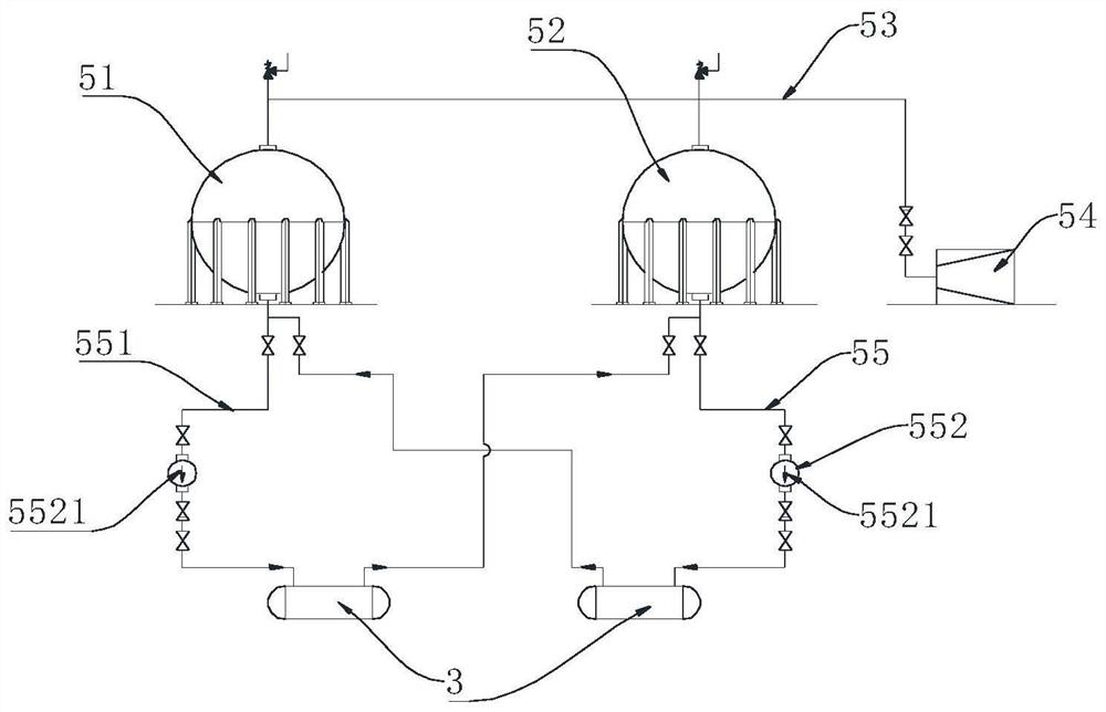
[0049] Such as figure 1 As shown, this embodiment provides a compressed air energy storage system using high-pressure and high-temperature hot water heat storage. The compressed air energy storage system includes a compressor 1, an expander 2, a heat exchanger 3, an air storage system 4 and a high-temperature The hot water heat storage and release system 5, the present invention adopts a multi-stage compression system and a multi-stage expansion system, that is, the present embodiment preferably adopts 4 compressors 1 and 3 expanders 2, wherein, the 4 compressors 1 are sequentially connected in series with The 4 inlets of the gas storage system are connected, and a heat exchanger 3 is connected to the outlet of each compressor 1; the 3 expanders 2 are connected in series with the 4 outlets of the gas storage system, and a heat exchanger 3 is connected to the inlet of each expander 2 heat exchanger 3. The high-temperature hot water heat storage and release system 5 is used to ...

Embodiment 2

[0067] Such as image 3 As shown, the difference between this embodiment and Embodiment 1 is that the high-temperature hot water storage and release system 5 of this embodiment is provided with three hot water storage tanks 51 and three cold water storage tanks 52, and the hot water storage tanks 51 and three cold water storage tanks are appropriately increased. The number of cold water storage tanks 52 can increase the energy storage and heat storage capacity of the system as a whole, and improve the energy storage and heat storage efficiency. Specifically, in order to supply the water transfer volume between the three hot water storage tanks 51 and the three cold water storage tanks 52, three one-way water pumps 5521 are arranged on each group of water transfer pipes 551 to improve the water transfer efficiency, that is, each The hot water storage tank 51 and each cold water storage tank 52 are respectively provided with a one-way water pump 5521 correspondingly.

Embodiment 3

[0069] Such as Figure 4 As shown, the difference between this embodiment and Embodiment 1 is that the high-temperature hot water heat storage and release system 5 of this embodiment is only provided with a set of water delivery system 55. Specifically, the water pump 552 in this embodiment adopts a bidirectional water pump 5522, whose It can be used to pump water from the hot water storage tank 51 to the cold water storage tank 52 through the heat exchanger 3 through the water delivery pipe 551 and to pump water from the cold water storage tank 52 to the hot water storage tank 51 through the heat exchanger 3, and the direction of water delivery can be switched.

[0070] Such as Figure 5 As shown, correspondingly, the compressor 1 and the expander 2 in the compressed air energy storage system of this embodiment are connected in parallel and share a set of heat exchangers 3, that is, when the compressor 1 is working, the inlet and outlet of the expander 2 are closed; When mac...


PUM


Abstract

The invention discloses a compressed air energy storage system adopting high-pressure and high-temperature hot water for heat storage and an operation method thereof.The compressed air energy storage system comprises a multi-stage air compressor, a multi-stage expansion machine, a plurality of heat exchangers, an air storage system and a high-temperature hot water heat storage and release system, and the high-temperature hot water heat storage and release system comprises a hot water storage tank, a cold water storage tank and an air supply mechanism; the gas supply mechanism is used for providing first-time filling high-pressure gas for the cold water storage tank and the hot water storage tank through a gas communicating pipe and maintaining the gas pressure in the tanks after the system runs; the cold water storage tank and the hot water storage tank are communicated through at least one water conveying system, each water conveying system comprises a water conveying pipe and a water pump, and the water pumps are used for pumping water from the hot water storage tank to the cold water storage tank through the water conveying pipes and / or pumping water from the cold water storage tank to the hot water storage tank through the heat exchangers. High-temperature hot water of 180 DEG C is adopted for heat storage, the problem that a heat storage system is high in investment is solved, and meanwhile the pressure maintaining problem of a high-pressure and high-temperature hot water heat storage and release system is solved.

Description

technical field [0001] The invention relates to the technical field of heat storage in a compressed air energy storage power station, in particular to a compressed air energy storage system using high-pressure and high-temperature hot water for heat storage and an operating method thereof. Background technique [0002] With the construction of more and more large-scale new energy bases, the new energy has a great impact on the power quality of the power transmission end due to the fluctuation of the scenery. Compared with traditional electrochemical energy storage, compressed air energy storage has the advantages of high safety, large adjustable capacity, and moment of inertia. Outward transmission is of positive significance, which can greatly improve the power grid's ability to absorb new energy and reduce the phenomenon of abandoning wind and light. [0003] Compressed air energy storage is in a stage of rapid development, and domestic research on the control strategy of...

Claims


Application Information

Patent Timeline
IPC IPC(8): F04B41/02F04B41/06F04B39/06F01K27/00F28D20/00
CPCY02E60/14Y02E60/16
Inventor 张春琳李峻韩亮阮刚陈牧
Owner CENT SOUTHERN CHINA ELECTRIC POWER DESIGN INST CHINA POWER ENG CONSULTING GROUP CORP
Learn More