Coordinate debugging method and system and storage medium

A debugging method and coordinate technology, which can be used in control/adjustment systems, general control systems, instruments, etc., and can solve problems such as cumbersome operations, collisions, and cumbersome operations.

Pending Publication Date: 2022-04-12
SHENZHEN REETOO BIOTECHNOLOGY CO LTD
View PDF0 Cites 0 Cited by
  • Summary
  • Abstract
  • Description
  • Claims
  • Application Information

AI Technical Summary

Problems solved by technology

When debugging a coordinate requires multiple motors to act in concert, the debugging engineer needs to turn pages back and forth on the debugging interface. The operation is cumbersome. If multiple motors are on different boards, it will lead to more cumbersome operations.
If it is required to accurately set the position parameters corresponding to each motor and the action sequence of each motor, it is necessary for the commissioning engineer to be very familiar with the equipment and the commissioning software to do so, otherwise it will easily cause various unexpected errors, even in the case of input errors. The action data will cause the phenomenon of collision

Method used


Image

  • Coordinate debugging method and system and storage medium
  • Coordinate debugging method and system and storage medium
  • Coordinate debugging method and system and storage medium

Examples


Embodiment 1

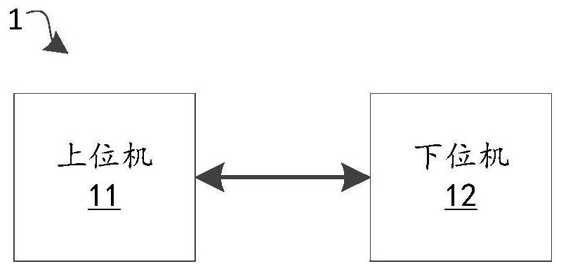
[0030] Please refer to figure 1 , this embodiment discloses a debugging system, which includes a communication-connected upper computer 11 and a lower computer 12, which will be described separately below.

[0031] In this embodiment, in this embodiment, the upper computer 11 may be a processing device to be displayed, such as a computer, a tablet, a workstation, etc., which may be installed with debugging software for the lower computer 12 . The user only needs to perform input operations and trigger operations on the upper computer 11 to start the debugging work for the lower computer 12 .

[0032]In this embodiment, the lower computer 12 can be medical testing equipment for testing samples, such as blood analyzers, urine analyzers, excrement analyzers, human tissue analyzers, sperm morphology analyzers, gynecological endocrine analyzers, etc. The interior of such medical testing equipment often has operations such as scanning, sampling, adding samples, cleaning, sample del...

Embodiment 2

[0038] A coordinate debugging method is disclosed in this embodiment, the coordinate debugging method is mainly in figure 1 It is applied on the upper computer 11 shown in , and realizes the corresponding coordinate debugging function.

[0039] In this example, please refer to Figure 4 , the disclosed coordinate debugging method includes steps S210-S250, which are respectively described as follows.

[0040] Step S210, the host computer sends a reading signal to the lower computer to obtain the original position parameters of one or more motors in the lower computer. One or more motors set in the lower computer are used to coordinately adjust the moving state of a component.

[0041] In this example, see figure 1 , the upper computer 11 can determine which original configuration parameters of the motors need to be obtained from the lower computer 12 through a preset configuration file. This configuration file can be stored in the lower computer 12, then directly read from ...

Embodiment 3

[0071] This embodiment discloses a debugging control method for the lower computer, the debugging control method is mainly in figure 1 It is applied on the lower computer 12 shown in , and realizes the corresponding debugging control function.

[0072] In this example, please refer to Figure 7 , the disclosed debugging control method may include steps S310-S350, which are respectively described as follows.

[0073] In step S310, the lower computer collects the original position parameters of one or more motors and sends them to the upper computer in response to the reading signal sent by the upper computer. Here one or more motors are used to coordinately adjust the movement state of a component.

[0074] In a specific example, see figure 1 , the lower computer 12 reads the motion board data of each motor according to the reading signal from the upper computer 11, where the motion board data exists on the corresponding motion board (control circuit board) of the motor and ...


PUM


Abstract

The invention relates to a coordinate debugging method and system and a storage medium. The coordinate debugging method comprises the following steps: sending a reading signal to obtain original position parameters of one or more motors; sending a reset signal to control each motor to act and adjusting the assembly to reset to the initial coordinate; sending a test signal to adjust the assembly to move to a preset coordinate; judging whether to send a fine tuning signal to adjust the assembly to move to a target coordinate; and updating according to the position parameter of each motor when the assembly arrives at the target coordinate to obtain a new position parameter of each motor. According to the technical scheme, a humanized interactive operation mode is provided, a user can complete coordinate debugging of a certain component only by performing simple operation on a debugging interface, operation steps are simplified, and the debugging efficiency of the lower computer is improved; besides, the method is high in universality, and method transplantation among different test items can be realized, so that the equipment debugging cost before the medical detection equipment leaves a factory is reduced.

Description

technical field [0001] The invention relates to the technical field of medical testing equipment, and in particular to a coordinate debugging method, a debugging system, and a storage medium. Background technique [0002] Existing medical testing equipment often contains a lot of execution parts, and these execution parts cooperate with each other to realize the functions of sample delivery, sampling, inspection, and sample discarding. Since each execution part needs to be driven by a motor, and Move the corresponding components (such as sampling needles, test strips, grippers, etc.) to the designated positions, so it is particularly important to debug the motors and components in the equipment before leaving the factory. Necessary process for proper functioning. [0003] In the debugging process of medical testing equipment, the modules are usually divided into motion boards and motors. For example, enter the number of steps in the box corresponding to the "Test" button, c...

Claims


Application Information

Patent Timeline
Patent Type & Authority Applications(China)
IPC IPC(8): G05B15/02G01N35/00
Inventor 黄继然吴照栋石义康唐继奎
Owner SHENZHEN REETOO BIOTECHNOLOGY CO LTD
Why Eureka
Try Eureka