
Electronic brake implementation method based on d-axis current controller and servo driver thereof

A servo drive, electronic braking technology, applied in the direction of controlling electromechanical brakes, controlling electromechanical transmission devices, controlling generators, etc., can solve problems such as unfavorable product maintenance, high maintenance and repair costs, and easily damaged braking resistors, and achieve convenient product maintenance. The effect of maintenance and reduction of product cost

Pending Publication Date: 2022-04-12
HANGZHOU ZHISHAN INTELLIGENT CONTROL TECH
View PDF0 Cites 0 Cited by
  • Summary
  • Abstract
  • Description
  • Claims
  • Application Information

AI Technical Summary

Problems solved by technology

[0003] 1. The cost is high, and it is necessary to drive the optocoupler + power tube + braking resistor through the braking circuit to achieve braking;
[0004] 2. It is not conducive to product maintenance. In the application of frequent braking, the braking resistor is easy to be damaged, and the maintenance cost is high.

Method used


Image

  • Electronic brake implementation method based on d-axis current controller and servo driver thereof
  • Electronic brake implementation method based on d-axis current controller and servo driver thereof
  • Electronic brake implementation method based on d-axis current controller and servo driver thereof

Examples


Embodiment Construction

[0032] The present invention will be described in further detail below in conjunction with the accompanying drawings and specific embodiments.

[0033] The solution provides a servo driver capable of realizing the electronic braking function based on the d-axis current controller, and the electronic braking function based on the d-axis current controller realized by the servo driver.

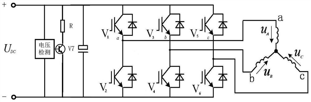
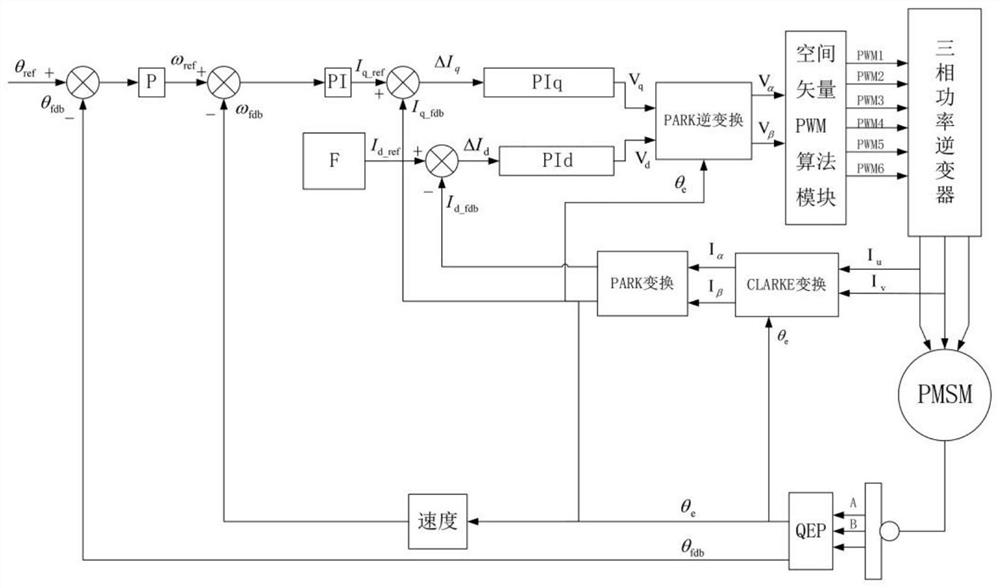
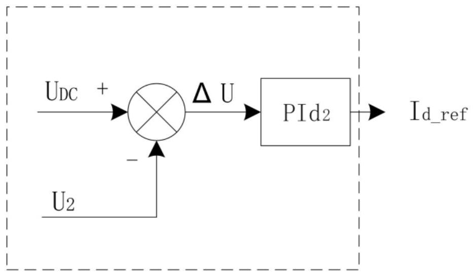
[0034] This scheme is realized by using the vector control of the servo driver, borrowing the existing vector control process of the servo driver, and changing the bus voltage U related to the brake on the basis of the vector control DC The vector control process is added to realize software braking, so that the energy generated by the motor braking can be converted into the copper loss and iron loss of the motor through the d-axis current. There is no need to install additional braking circuits, which improves the efficiency while reducing costs. System maintainability.

[0035] Such as figu...


PUM


Abstract

The invention provides an electronic braking implementation method based on a d-axis current controller and a servo driver thereof, the servo driver comprises a position loop, a rotating speed loop, a q-axis current loop, a d-axis current loop, a space vector PWM algorithm module and an inverter connected to a motor, the d-axis current loop is used for outputting a d-axis voltage signal Vd according to a d-axis current given value Idref and a d-axis current detection value Idfdb, the d-axis current loop is connected with a d-axis second current loop, and the d-axis current given value Idref is determined by the d-axis second current loop according to the bus voltage UDC. The method of the d-axis current controller is adopted, the braking function of the motor is achieved through a software program, an additionally-installed braking circuit can be omitted, the product cost is reduced, and product maintenance is facilitated.

Description

technical field [0001] The invention belongs to the technical field of motor braking, and in particular relates to an electronic braking realization method based on a d-axis current controller and a servo driver thereof. Background technique [0002] Such as figure 1 As shown, the traditional permanent magnet synchronous motor braking system uses a braking resistor to achieve braking. When the motor brakes and decelerates, the energy of the motor is fed back to the DC circuit to increase the bus voltage. When the bus voltage reaches the voltage value set by the driver At this time, the power tube V7 is turned on, the kinetic energy of the motor is converted into heat energy through the braking resistor R and consumed, and the bus voltage will also decrease accordingly. When the bus voltage drops to the set value, the power tube is cut off, and the braking resistor stops working. There are certain defects in this braking method, for example: [0003] 1. The cost is high, an...

Claims


Application Information

Patent Timeline
IPC IPC(8): H02P21/36H02P25/026H02P27/08
Inventor 王刚志燕婧婧马晓伟
Owner HANGZHOU ZHISHAN INTELLIGENT CONTROL TECH
Features
  • Generate Ideas
  • Intellectual Property
  • Life Sciences
  • Materials
  • Tech Scout
  • Unparalleled Data Quality
  • Higher Quality Content
  • 60% Fewer Hallucinations
Learn More