Intelligent drilling robot
A robot and intelligent technology, applied in drilling equipment and methods, drilling equipment, earth-moving drilling, etc., can solve the problems of safety risks for drilling personnel, high labor intensity of workers, easy to cause occupational diseases, etc., and improve drilling efficiency. 、Enhanced punching efficiency, flexible and convenient operation control
- Summary
- Abstract
- Description
- Claims
- Application Information
AI Technical Summary
Problems solved by technology
Method used
Image

Examples
Embodiment 1
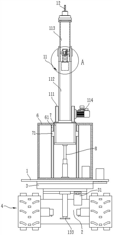
[0037] This embodiment provides an intelligent drilling robot, such as Figure 1-3As shown, including a walking chassis 2 and a drilling device located on the walking chassis 2, the walking chassis 2 of the present embodiment adopts a crawler-type walking chassis, which makes the overall equipment walk more stable, and the two sides of the walking chassis 2 are walking crawlers 4, so that The walking on both sides of the equipment is more consistent, and it is more convenient to control. The drilling device is arranged on the walking chassis 2 through a slewing mechanism, and the slewing mechanism can allow the drilling device on the upper side to perform a 360° rotary motion relative to the walking chassis 2, so as to adjust the position more conveniently. The slewing mechanism includes The rotary platform 1 and the rotary drive assembly for driving the rotary table 1 to rotate, the rotary platform 1 is arranged on the walking chassis 2 through the rotary support 3, the rotar...
Embodiment 2
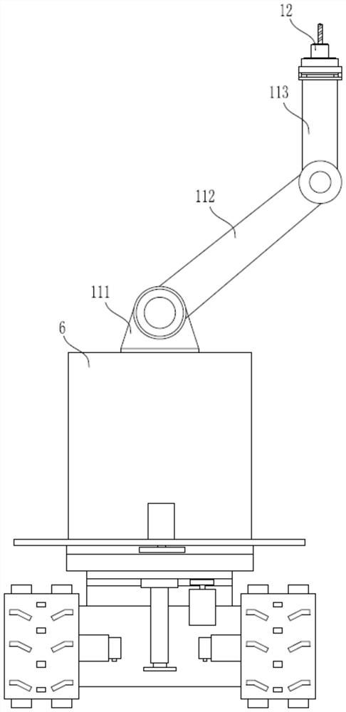
[0044] Such as Figure 5 As shown, compared with Embodiment 1, the main difference of Embodiment 2 is that: the multi-axis manipulator includes a side outrigger 116, and the side outrigger 116 includes two support arms that are fixedly connected, and the two support arms There is a certain angle between them, generally a right angle or an obtuse angle. One end of the side outrigger 116 is fixedly connected to the lifting mechanism, the other end of the side outrigger 116 is set upward, and the drilling tool 12 is arranged on the side outrigger 116. Top. The structure of this embodiment is simpler than that of Embodiment 1. Through the setting of the side arm 116, the top punching operation at the edge of the wall and the corner is realized through a simple structure.
Embodiment 3
[0046] Such as Figure 6-9 As shown, compared with the first embodiment, the main difference of the third embodiment is that the multi-axis mechanical arm 11 is arranged on the lifting support 7 through a lateral movement assembly, and the lateral movement assembly includes a lateral movement seat 9 and a lateral guide rail 72 , the lateral guide slider 91 and the lateral drive mechanism 10, the lateral guide rail 72 is fixedly installed in the lifting bracket 7 along the lateral direction, the laterally moving seat 9 is slidably connected with the lateral guide rail 72 through the lateral guide slider 91, and the lateral guide rail 72 is slidably connected. The driving mechanism 10 includes a driving toothed rotating shaft 103, a passive toothed rotating shaft 104 and a toothed belt 102 supported between the two toothed rotating shafts. The driving toothed rotating shaft 103 is fixedly connected to a transverse drive motor 101, and the lateral movement The lower end of the se...
PUM
 Abstract
Description
Claims
Application Information
 - Generate Ideas
- Intellectual Property
- Life Sciences
- Materials
- Tech Scout
- Unparalleled Data Quality
- Higher Quality Content
- 60% Fewer Hallucinations
Browse by: Latest US Patents, China's latest patents, Technical Efficacy Thesaurus, Application Domain, Technology Topic, Popular Technical Reports.
© 2025 PatSnap. All rights reserved.Legal|Privacy policy|Modern Slavery Act Transparency Statement|Sitemap|About US| Contact US: help@patsnap.com