Waveform peak value sampling circuit

A peak sampling and waveform technology, applied in the industrial field, can solve the problems of holding, affecting the peak sampling result, and increasing the complexity of the peak sampling circuit, achieving the effect of high generalization level and simple circuit structure

Pending Publication Date: 2022-04-15
XIAN AVIATION COMPUTING TECH RES INST OF AVIATION IND CORP OF CHINA
View PDF0 Cites 0 Cited by
  • Summary
  • Abstract
  • Description
  • Claims
  • Application Information

AI Technical Summary

Problems solved by technology

A typical peak sampling circuit is generally composed of a voltage follower, a diode, a resistor, and a capacitor. Using the combination of the unidirectional conduction characteristic of the diode and the amplification performance of the amplifier, the input sine wave signal is rectified, and the capacitor is continuously charged until the two ends of the capacitor When the voltage reaches the peak value of the sine wave, an analog-to-digital converter is used to collect the voltage across the capacitor. However, the defect of this circuit is that once the voltage across the capacitor is charged to the peak value, it will remain there, which will affect the subsequent peak sampling. As a result, this peak sampling circuit also needs to configure a special charge discharge circuit, which leads to an increase in the complexity of the peak sampling circuit

Method used


Image

  • Waveform peak value sampling circuit
  • Waveform peak value sampling circuit
  • Waveform peak value sampling circuit

Examples


Embodiment 1

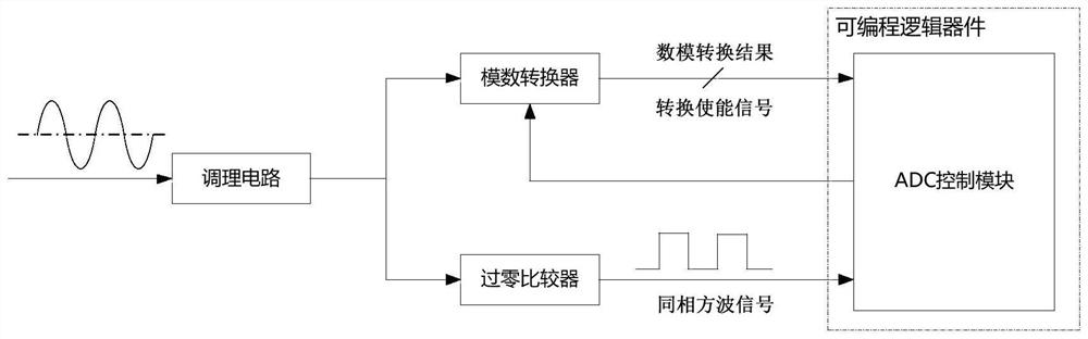
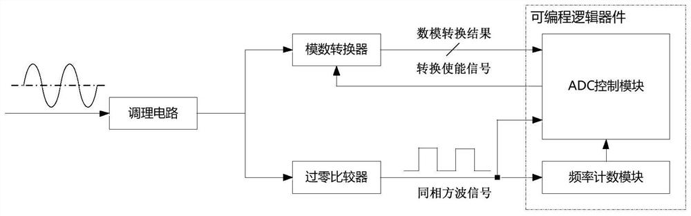
[0021] like figure 2 As shown, the technical solution of the present invention: a waveform peak sampling circuit, the waveform peak sampling circuit includes a conditioning circuit, an analog-to-digital conversion circuit, a zero-crossing comparator, an ADC control module and a frequency counting module, wherein: the input of the conditioning circuit Connect to the waveform to be sampled; the output of the conditioning circuit is connected to the analog input pin of the analog-to-digital conversion circuit and the input pin of the zero-crossing comparator; the output of the digital-to-analog conversion result of the analog-to-digital conversion circuit is connected to the input of the ADC control module ; The output of the zero-crossing comparator is respectively connected to the input of the ADC control module and the frequency counting module; the output of the frequency counting module is connected to the input of the ADC control module. The conversion enable output of the...

Embodiment 2

[0042] The invention is suitable for the peak value collection of sine waves with known frequency and the peak value collection of sine waves with unknown frequency.

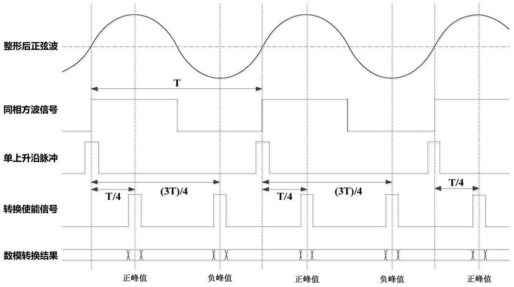
[0043] First, combine figure 1 and image 3 Describe the peak sampling process for a sine wave of known frequency. The sine wave input signal is input to the conditioning circuit, and after filtering the DC interference and high-frequency burr coupled on the sine wave input signal, it is input to the analog-to-digital converter and the zero-crossing comparator at the same time. One of the zero-crossing comparators is a single-ended comparison device whose reference voltage is "ground level". When its input is a sine wave after shaping and filtering, its output is a square wave signal with the same phase as the sine wave after shaping and filtering. Input the square wave signal with the same phase as the shaped and filtered sine wave to the ADC control module, and the ADC control module uses the rising edge mom...


PUM


Abstract

The invention belongs to the field of circuit electronics, and particularly relates to a waveform peak value sampling circuit. The waveform peak value sampling circuit is composed of a conditioning circuit, an analog-to-digital converter, a zero-crossing comparator, an ADC control module and a frequency counting module, wherein the ADC control module and the frequency counting module are realized based on a programmable logic device. A zero-crossing comparator is configured to generate a square wave signal with the same phase as a sine wave signal after shaping and filtering, the rising edge moment of the square wave signal with the same phase serves as a 0-degree phase point of a sine wave input signal, analog-to-digital conversion is enabled at 90-degree and 270-degree phase positions respectively according to a count value of a sine wave period output by a frequency counting module, and the sine wave signal is converted into a sine wave signal. The sine wave positive peak value and negative peak value sampling circuit is simple in structure, high in generalization level and capable of being widely applied to the industrial field.

Description

technical field [0001] The invention relates to the industrial field, in particular to a waveform peak sampling circuit. Background technique [0002] Waveform peak sampling circuits are widely used in industrial fields. A typical peak sampling circuit is generally composed of a voltage follower, a diode, a resistor, and a capacitor. Using the combination of the unidirectional conduction characteristic of the diode and the amplification performance of the amplifier, the input sine wave signal is rectified, and the capacitor is continuously charged until the two ends of the capacitor When the voltage reaches the peak value of the sine wave, an analog-to-digital converter is used to collect the voltage across the capacitor. However, the defect of this circuit is that once the voltage across the capacitor is charged to the peak value, it will remain there, which will affect the subsequent peak sampling. As a result, such a peak sampling circuit needs to be configured with a sp...

Claims


Application Information

Patent Timeline
Patent Type & Authority Applications(China)
IPC IPC(8): G01R19/04
Inventor 屈盼让张倩倩朱耀国呼明亮刘夏青孙少华
Owner XIAN AVIATION COMPUTING TECH RES INST OF AVIATION IND CORP OF CHINA
Why Eureka
Try Eureka