Liquid ejection nozzle

A technology for injecting nozzles and liquids, which is applied to fuel injection devices, special fuel injection devices, engine components, etc., and can solve problems such as increased flow spray, loss, and inability to achieve diffusion.

Pending Publication Date: 2022-04-19
ACR
View PDF3 Cites 0 Cited by
  • Summary
  • Abstract
  • Description
  • Claims
  • Application Information

AI Technical Summary

Problems solved by technology

The vicinity of the second outer seat portion is prone to elastic deformation due to improper force such as back pressure
Therefore, for the above-mentioned liquid injection nozzle, the kinetic energy of the swirling flow generated in the swirling flow chamber, that is, the vortex, is greatly lost when flowing from the disk-shaped swirling flow chamber into the nozzle hole, and the swirling flow generated in the disk-shaped swirl chamber The vortex flow generated in the flow chamber changes direction again at right angles to flow into the flow path of the nozzle hole in order to flow into the nozzle hole provided in the center of the disc-shaped swirl flow chamber, so a large loss of kinetic energy occurs here too.
In the above-mentioned liquid injection nozzle, the liquid in the liquid flow path flows into the swirling flow chamber from the thin hole in a tangential direction by the lifting and lowering of the needle valve to generate a swirl flow, that is, a swirl flow. However, in a state where the kinetic energy of the swirl flow is largely lost, the kinetic energy decreases. The vortex flow is sprayed from the nozzle hole to the outside, so that it is impossible to achieve a larger spray on the outside and increase the flow rate of the spray

Method used


Image

  • Liquid ejection nozzle
  • Liquid ejection nozzle
  • Liquid ejection nozzle

Examples


Embodiment Construction

[0030] The multi-nozzle structure of the liquid injection nozzle of the present invention is preferably applied to a nozzle for spraying a liquid such as a fuel injection device equipped with a diesel engine, an exhaust gas purification device for spraying a liquid such as ammonia water or urea water, or the like.

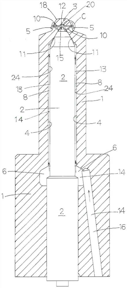
[0031] Hereinafter, embodiments of the liquid ejection nozzle will be described with reference to the drawings. First, refer to figure 1 and figure 2 , the schematic structure of the first embodiment of the liquid ejection nozzle will be described. This liquid injection nozzle can be applied to, for example, a fuel injection nozzle equipped with a diesel engine or a gasoline engine, or an exhaust gas purification device that sprays a liquid such as ammonia water or urea water. The liquid injection nozzle mainly includes: a tubular nozzle main body 1, which is fixed to the mounting portion of the engine, injection device, combustion equipment, etc., and has liqui...


PUM


Abstract

The present invention provides a liquid ejection nozzle which can reduce loss of kinetic energy and atomize and spray liquid, thereby promoting mixing with other gases and promoting reaction between the liquid and other gases. The liquid ejection nozzle is provided with a plurality of tip tips, each of which has an ejection hole, at the tip of a nozzle body. A swirling flow chamber is formed in the tip tip so as to surround the injection hole, and a fine hole is formed in the tip section so as to communicate with the tip of the conical surface of the swirling flow chamber of the tip tip from the tip-side wall surface on the tip side of the valve seat of the hollow section. By lifting and lowering the needle valve, the liquid in the liquid flow path flows into the swirling flow chamber from the communicating fine hole in the tangential direction to generate a swirling flow, and the swirling flow is sprayed to the outside from the spray hole.

Description

technical field [0001] The present invention relates to a liquid injection nozzle for injecting liquid such as fuel used in various devices such as engines, burners, and exhaust gas purifiers. Background technique [0002] Conventionally, liquid injection devices for injecting liquids such as fuel and ammonia water are used in engines, burners, exhaust gas purification devices, etc., and store liquid at high pressure, deliver the high-pressure liquid to the nozzle, and open it from the valve seat. The needle valve in the nozzle part is used to inject high-pressure liquid into the liquid spray chamber, combustion chamber and other chambers and spray the liquid. For example, a common rail fuel injection device can be applied to the latest engines because it can inject fuel over 2000 bar (bar) in multiple stages. As for the liquid ejection device, the biggest disadvantage of the liquid ejection system is high cost, and it can be said that the high cost of the parts of the ejec...

Claims


Application Information

Patent Timeline
Patent Type & Authority Applications(China)
IPC IPC(8): F02M61/18F02M61/10
CPCF02M61/18F02M61/10F02M61/162F02M61/1806F02B23/10F02M45/02F02M61/182F02M2200/46
Inventor 松冈宽野口宏岸下敬冶
Owner ACR
Why Eureka
Try Eureka