Combined impeller air compressor
An air compressor and combined technology, applied in mechanical equipment, electric components, electromechanical devices, etc., can solve the problems of untimely motor heat dissipation, limited motor speed, poor heat dissipation effect, etc., to improve efficiency, reduce friction, Achieving the effect of heat dissipation
- Summary
- Abstract
- Description
- Claims
- Application Information
AI Technical Summary
Problems solved by technology
Method used
Image
Examples
Embodiment 1
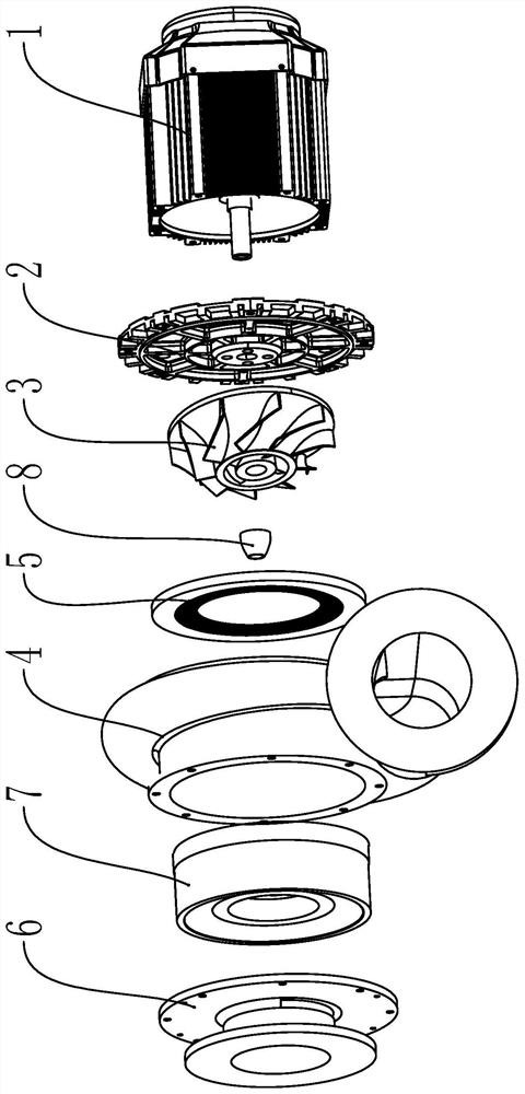
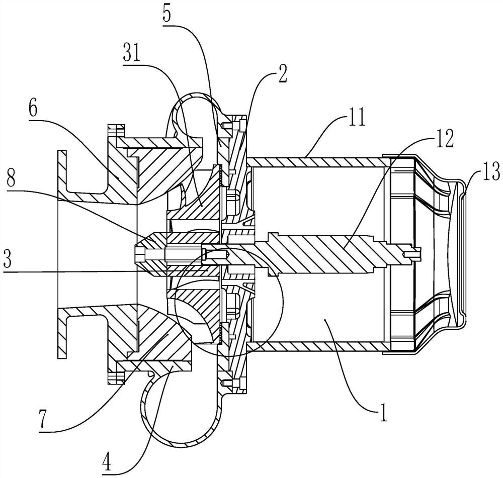
[0047] Embodiment 1: refer to Figure 1 to Figure 4 , a combined impeller air compressor, comprising:
[0048] The motor assembly 1 provides power for the air compressor; the motor assembly 1 includes a housing 11 and a rotating shaft 12, and the rotating shaft 12 is installed in the housing 11; the two ends of the rotating shaft 12 are respectively provided with a first end cover 2 and a second end cover 13. The first end cover 2 is connected to the housing 11 through bolts, and the second end cover 13 is a mesh shell cover, which is conducive to heat dissipation;
[0049] The impeller 3 includes a centrifugal impeller 31 and an axial impeller 32. The centrifugal impeller 31 is provided with a through hole 311 along the axial direction, and centrifugal blades 312 are arranged in the circumferential direction of the centrifugal impeller 31. The centrifugal impeller 31 is arranged in the through hole 311, and the axial impeller 32 Axial blades 32 are arranged in the circumfere...
Embodiment 2
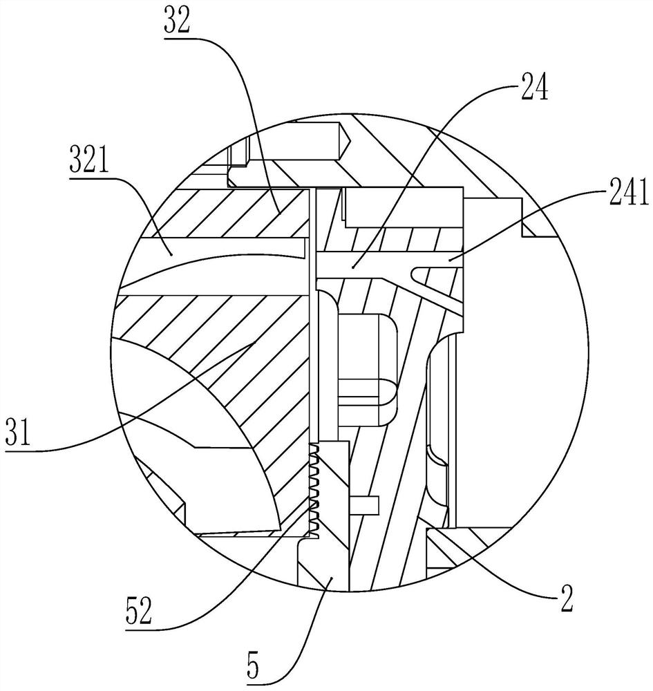
[0060] Embodiment 2: refer to Figure 5 , this embodiment is basically the same as Embodiment 1, the difference is that an annular sealing disc 5 is arranged between the impeller 3 and the first end cover 2, the sealing disc 5 is connected with the first end cover 2 by screws, and the sealing disc 5 is provided with a groove 51 matching with the bottom end surface of the impeller 3 .
[0061] When the air compressor is running, because the impeller 3 needs to rotate at a high speed, the impeller 3 cannot contact with parts other than the rotating shaft 12. In order to prevent the air from flowing between the first end cover 2 and the volute 4 Therefore, a sealing disc 5 is provided to prevent air from leaking out from the gap between the first end cover 12 and the volute 4 through the groove 51 on the sealing disc 5 and the groove 51 matched with the end face of the impeller 3; Air compressor efficiency.
[0062] The groove 51 is provided with a plurality of sealing ring gea...
Embodiment 3
[0064] Embodiment 3: refer to Figure 6 and Figure 7 , the structure of this implementation is basically the same as that of Embodiment 1 or Embodiment 2, except that:
[0065] The first end cap 2 includes:
[0066] The first end surface 21 is matched with the housing 11, and a first protruding ring 211 which can be matched with the inner diameter of the housing 11 is provided in the circumferential direction;
[0067] The second end surface 22 is matched with the volute 4, and the second protruding ring 221 and the third protruding ring 222 are arranged in the circumferential direction;
[0068] The convex plate 23 protrudes from both ends of the first end surface 21 and the second end surface 22 along the axial direction of the first end cover 2 . The convex plate 23 is provided with a through hole 231 , and the rotating shaft 12 passes through the through hole 231 .
[0069] The first end cover 2 is a part connecting the housing 11 and the impeller 3, and the first prot...
PUM
 Abstract
Description
Claims
Application Information
 - R&D
- Intellectual Property
- Life Sciences
- Materials
- Tech Scout
- Unparalleled Data Quality
- Higher Quality Content
- 60% Fewer Hallucinations
Browse by: Latest US Patents, China's latest patents, Technical Efficacy Thesaurus, Application Domain, Technology Topic, Popular Technical Reports.
© 2025 PatSnap. All rights reserved.Legal|Privacy policy|Modern Slavery Act Transparency Statement|Sitemap|About US| Contact US: help@patsnap.com


