Multi-objective optimization array directional diagram synthesis method based on improved genetic algorithm

A multi-objective optimization and genetic algorithm technology, applied in the field of multi-objective optimization array pattern synthesis based on improved genetic algorithm, can solve the problems of easy local convergence, inability to search for amplitude-phase weighted values, slow convergence speed, etc. Improve convergence speed, improve optimization effect, low sidelobe effect

Pending Publication Date: 2022-04-22
NO 54 INST OF CHINA ELECTRONICS SCI & TECH GRP
View PDF0 Cites 0 Cited by
  • Summary
  • Abstract
  • Description
  • Claims
  • Application Information

AI Technical Summary

Problems solved by technology

However, due to the problems of the Hamming cliff, easy local convergence, and slow convergence speed, the

Method used


Image

  • Multi-objective optimization array directional diagram synthesis method based on improved genetic algorithm
  • Multi-objective optimization array directional diagram synthesis method based on improved genetic algorithm
  • Multi-objective optimization array directional diagram synthesis method based on improved genetic algorithm

Examples


Embodiment 1

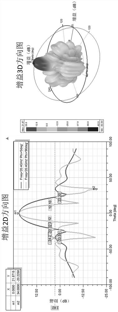
[0056] Taking the 8×16 X-band right-hand circularly polarized microstrip antenna array as an example, the beam nulling synthesis problem with controllable sidelobes is solved. In the airborne phased array antenna, in order to reduce the probability of being detected, the sidelobe level is required to be low enough; and the beam anti-interference is performed by forming a null in a known interference direction. According to the system index requirements, the index requirement for determining the far-field pattern of the array is that the sidelobe level is less than 18dB; and θ=±34°The depth of null trap formed in the interference direction is greater than 40dB. In order to reduce the amount of calculation on the basis of ensuring the comprehensive performance of the array, and the weighted distribution of the amplitude and phase has been determined to be axisymmetric about the vertical and horizontal directions of the array according to prior knowledge, and according to the lo...

Embodiment 2

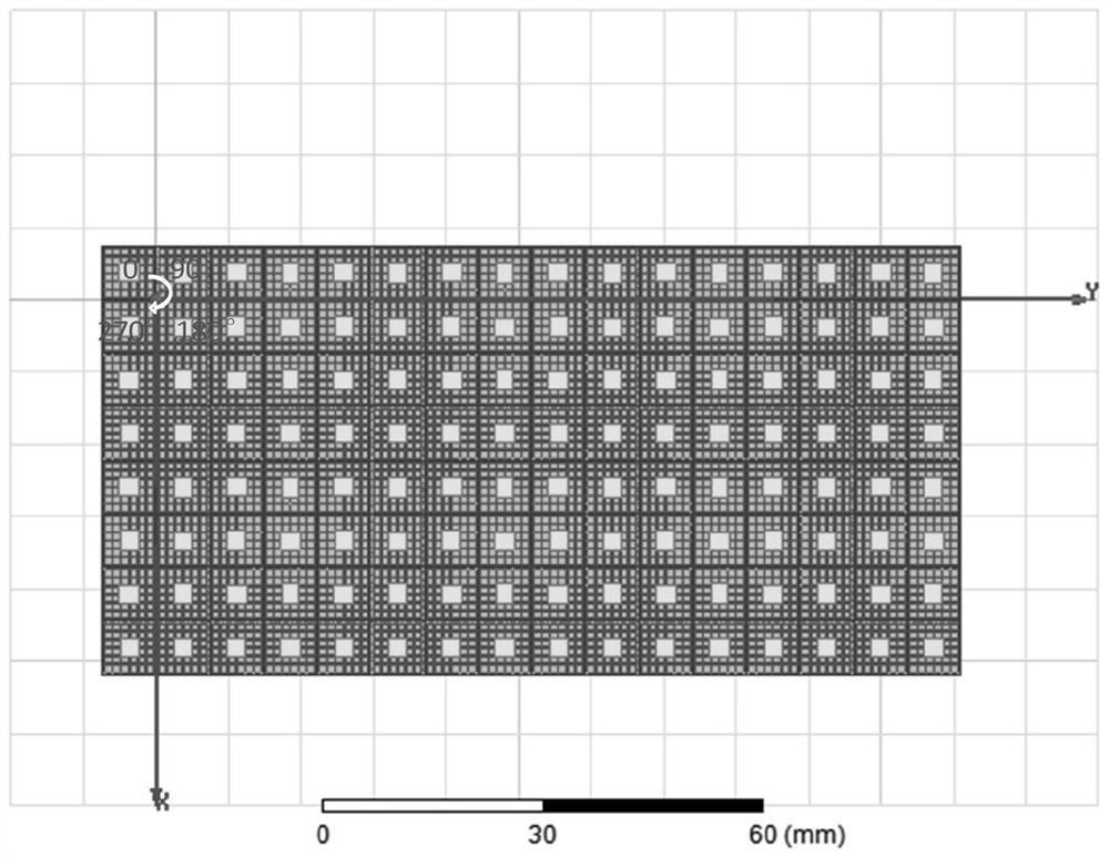
[0074] Taking the 16×16 Ka-band linearly polarized microstrip antenna array as an example, the problem of flat-top beam synthesis with controllable sidelobes is solved. In the base station antenna, larger beam width and lower side lobe level are required to ensure that the antenna still has higher gain at low elevation angles. According to the system index requirements, the index requirements for determining the far-field pattern of the array are 3dB beam width of 48° and sidelobe level less than 17dB. In order to reduce the amount of calculation on the basis of ensuring the comprehensive performance of the array, and the weighted distribution of the amplitude and phase has been determined to be symmetrical about the center of the array based on prior knowledge, we can only consider and Array pattern in two directions. According to the requirements of the index, the optimization goal of the far-field pattern is finally determined as In the direction, the 3dB beamwidth is 4...


PUM

PropertyMeasurementUnit
Beam widthaaaaaaaaaa

Abstract

The invention discloses a multi-objective optimization array pattern synthesis method based on an improved genetic algorithm, and belongs to the field of antenna array pattern synthesis. According to the method, the genetic algorithm is improved and optimized, and in order to avoid local convergence and prevent close-to-close combination, the Hamming distance is introduced to carry out close-to-close discrimination; in order to improve the convergence speed and ensure that an excellent mode in a parent body can be inherited to the next generation, the size of a crossover operator is adaptively determined according to the fitness. According to the method, a mutual coupling effect between array elements is considered, an active unit directional diagram is combined, an accurate antenna array model is constructed, different fitness function parameters are set for different target array directional diagrams, and an improved genetic algorithm is used for performing multi-target rapid optimization on the antenna array directional diagrams; finally, array synthesis such as beam broadening, low sidelobe, beam null, phased array scanning and the like is realized, and verification is carried out through full-wave electromagnetic simulation software.

Description

technical field [0001] The invention belongs to the technical field of antenna array pattern synthesis, in particular to a multi-objective optimized array pattern synthesis method based on an improved genetic algorithm. Background technique [0002] Array antennas are widely used in radar, communication, navigation and positioning and other fields because they can perform beamforming according to different application scenarios to improve system performance. In order to obtain a pattern that meets specific requirements, many array synthesis algorithms are used to solve the excitation amplitude and phase values ​​of the array antenna radiating elements, mainly including analytical methods, numerical methods, and intelligent optimization algorithms. Compared with the traditional array synthesis algorithm, the intelligent optimization algorithm has the advantages of global search, dynamic adjustment of the objective function, and simultaneous optimization of multiple objectives...

Claims


Application Information

Patent Timeline
IPC IPC(8): G06F30/20G06N3/12
CPCG06F30/20G06N3/126
Inventor 赵琪魏浩韩威魏恒王亚舟周媛卢云龙赵建欣刘子奕
Owner NO 54 INST OF CHINA ELECTRONICS SCI & TECH GRP
Why Eureka
Try Eureka