Cross-season phase change energy storage system
A phase-change energy storage and inter-seasonal technology, applied in the field of inter-seasonal phase-change energy storage systems, can solve problems such as poor technical applicability, low energy efficiency, and limited energy resources, so as to improve equipment utilization, reduce operating costs, and realize The effect of reuse
- Summary
- Abstract
- Description
- Claims
- Application Information
AI Technical Summary
Problems solved by technology
Method used
Image
Examples
Embodiment 1
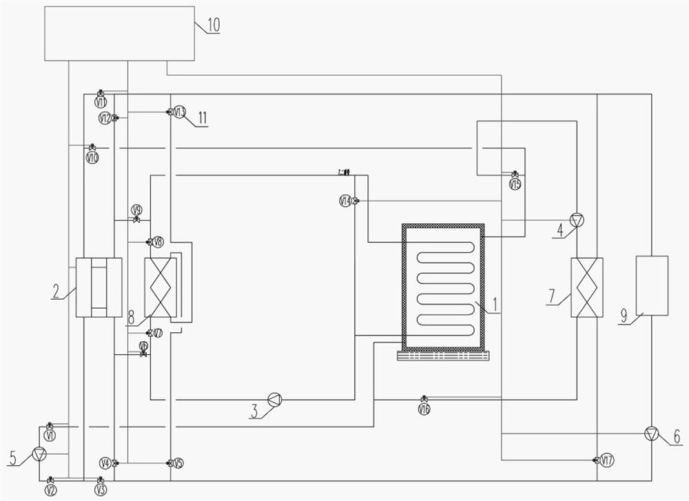
[0029] refer to figure 1 , 2 , which is the first embodiment of the present invention, this embodiment provides an interseasonal phase change energy storage system, including an automatic control device 10 and a valve group 11 electrically connected to the automatic control device 10, and the automatic control device 10 is connected to a water source The heat pump 2 and the water source heat pump 2 are respectively connected to the thermal storage circulating water pump 5, the air conditioning circulating water pump 6, the winter energy release plate 7, and the building air conditioning terminal 9 through the valve group 11;
[0030] The automatic control device 10 is connected with the water source energy releasing circulating water pump 4, and the water source energy releasing circulating water pump 4 is respectively connected with the air conditioner circulating water pump 6, the winter energy releasing plate changer 7 and the interseasonal phase change energy storage devic...
Embodiment 2
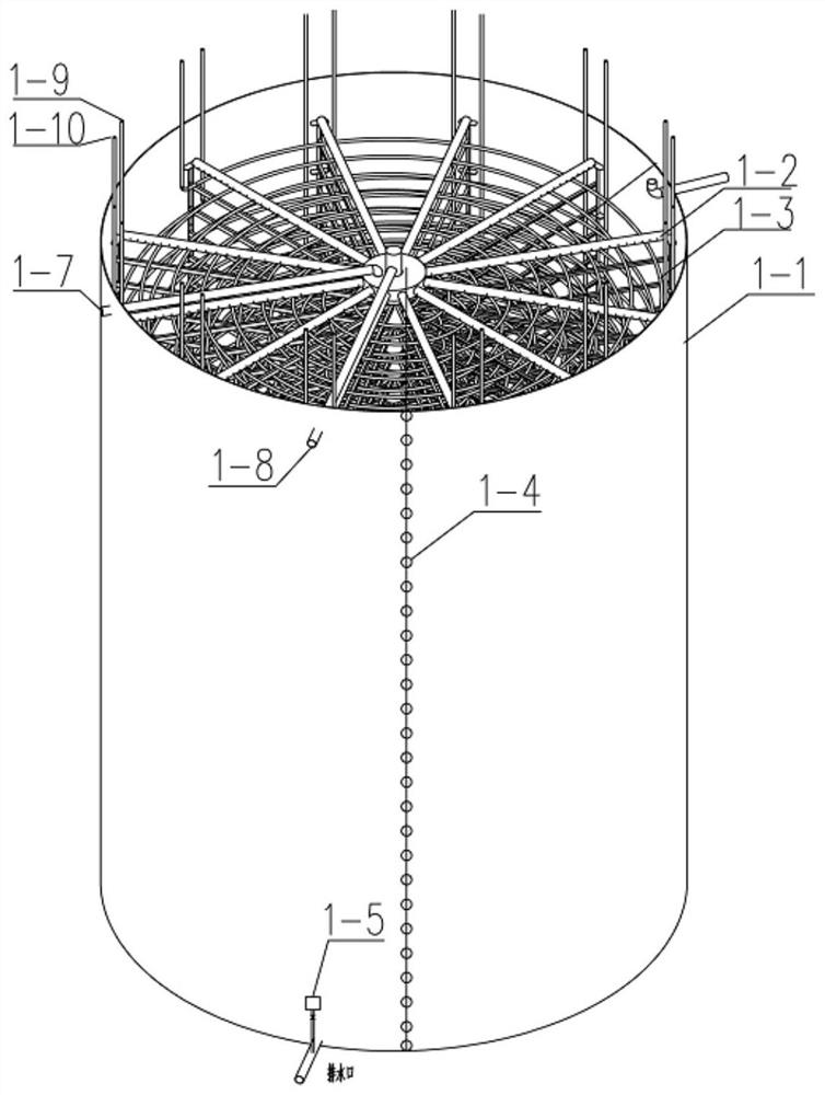
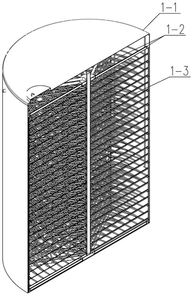
[0033] refer to Figure 1-4 , which is the second embodiment of the present invention. This embodiment is based on the previous embodiment. Specifically, the water source heat pump 2 has an evaporator, a condenser, a compressor, and a throttling device, which is switched by an internal valve and has the function of dual working conditions. It can cool buildings in summer and prepare hot water at the same time, and heat buildings in winter while preparing ice water.
[0034] Specifically, the valve group 11 is composed of a number of solenoid valves numbered V1-V17, and each solenoid valve is electrically connected to the automatic control device 10, so that each valve can be controlled on and off by the automatic control device 10.
[0035] Specifically, inter-seasonal phase change energy storage device 1, water source heat pump 2, ice water circulating water pump 3, water source energy releasing circulating water pump 4, heat storage circulating water pump 5, air conditioning...
Embodiment 3
[0045] refer to Figure 1-4 , which is the third embodiment of the present invention. This embodiment is based on the above two embodiments. When in use, each control unit of the automatic control device 10 is used to realize the setting of each device and the opening of the electromagnetic valve to achieve the conversion of different working conditions. , working condition 1: summer cooling and thermal storage working condition, the automatic control device 10 gives a signal, the water source heat pump 2, the heat storage circulating water pump 5, the air conditioning circulating water pump 6, and the solenoid valves are numbered V1, V2, V4, V10, and V14. , the evaporator of the water source heat pump 2, the building air conditioning terminal 9, and the air conditioning circulating water pump 6 are connected through pipelines after the valve V4 and valve V12 are opened, so as to realize the purpose of cooling the building air conditioning terminal 9; at the same time, the wate...
PUM
 Abstract
Description
Claims
Application Information
 - R&D
- Intellectual Property
- Life Sciences
- Materials
- Tech Scout
- Unparalleled Data Quality
- Higher Quality Content
- 60% Fewer Hallucinations
Browse by: Latest US Patents, China's latest patents, Technical Efficacy Thesaurus, Application Domain, Technology Topic, Popular Technical Reports.
© 2025 PatSnap. All rights reserved.Legal|Privacy policy|Modern Slavery Act Transparency Statement|Sitemap|About US| Contact US: help@patsnap.com


