

Rapid drilling device for air compressor production
A drilling device and air compressor technology, applied in positioning devices, boring/drilling, drilling dies for workpieces, etc., can solve the problem of affecting workpiece installation, difficulty in replacing drill bit guides, and reducing machining efficiency and machining accuracy. and other problems, to achieve the effect of facilitating positioning and installation, improving drilling efficiency, and improving processing efficiency
- Summary
- Abstract
- Description
- Claims
- Application Information
AI Technical Summary
Problems solved by technology
Method used
Image

Examples
Embodiment Construction
[0021] The following will clearly and completely describe the technical solutions in the embodiments of the present invention with reference to the accompanying drawings in the embodiments of the present invention. Obviously, the described embodiments are only some, not all, embodiments of the present invention. Based on the embodiments of the present invention, all other embodiments obtained by persons of ordinary skill in the art without making creative efforts belong to the protection scope of the present invention.
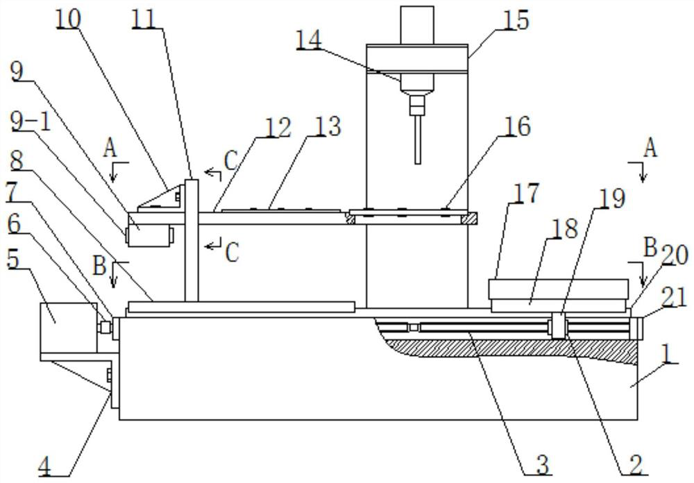
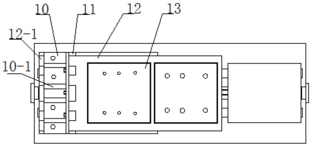
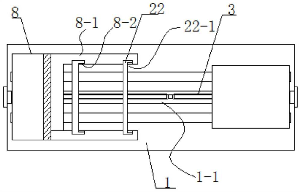
[0022] Such as Figure 1 to Figure 3 As shown, a quick drilling device for air compressor production includes a machine tool workbench 1, one side of the machine tool workbench 1 is provided with a drill arm 15, and a drill bit 14 is installed on the drill arm.
[0023] A pair of dovetail slide rails 20 are fixed on the upper surface of the machine tool table 1, and a track groove 1-1 is also provided on the upper surface of the machine tool table 1. The trac...
PUM
 Abstract
Description
Claims
Application Information