[0039] The technical solutions in the embodiments of the present invention will be clearly and completely described below with reference to the accompanying drawings in the embodiments of the present invention.
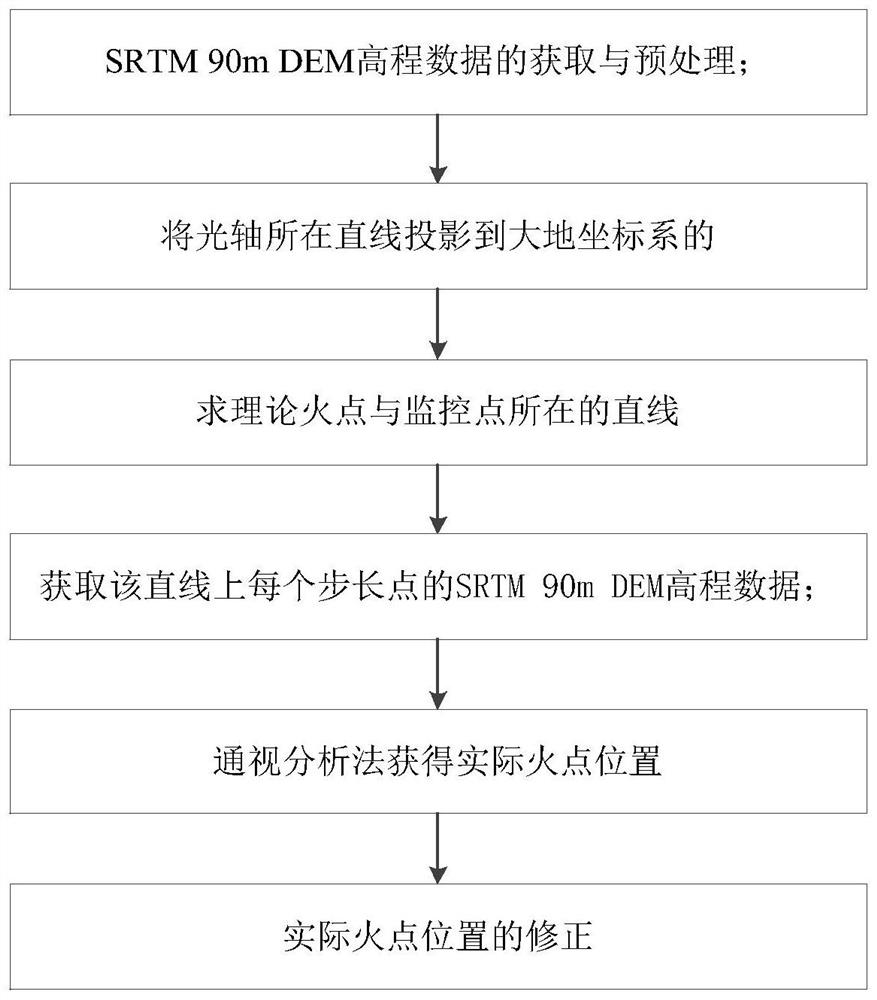
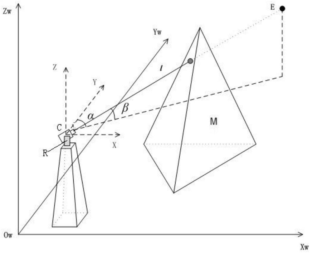
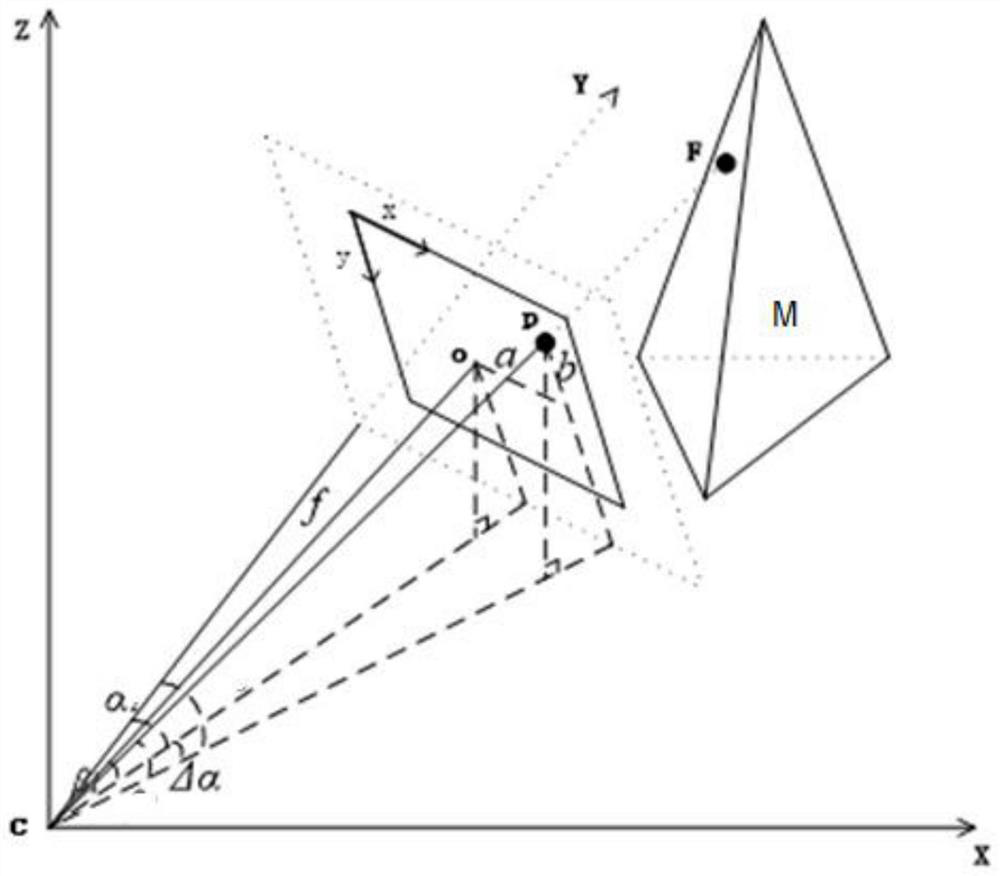
[0040] The invention provides a single ignition point positioning method based on SRTM 90m DEM, such as figure 1 shown, including the following steps:
[0041] (1) Acquire SRTM 90m DEM elevation data and preprocess it; data preprocessing includes format conversion, coordinate conversion, data editing, vectorization conversion and data block in turn.
[0042] Format conversion realizes the unified conversion of img and other format data into TIF format; coordinate transformation converts the coordinate system into coordinates consistent with the gis display platform, and realizes the conversion between coordinate systems such as WGS84, GCJ02, BD09, etc.; The part of the elevation data that changes due to the engineering is corrected; the vectorization conversion realizes the vectorization of the scattered point elevation data into the surface data with the height value, so as to realize the collision calculation more quickly in the later stage; the data is divided into blocks according to the effective monitoring range of each monitoring point Data segmentation is performed to match the segmented data to the corresponding monitoring points, thereby improving computing efficiency.
[0043] (2) When the monitoring equipment monitors the theoretical fire point on the mountain peak, the pan/tilt stops rotating, the camera shoots the current picture, and projects the straight line where the optical axis is located at the current moment from the mechanical horizontal coordinate system to the geodetic coordinate system;
[0044] The specific method is as follows:
[0045] like figure 2As shown, the monitoring equipment is the camera C set on the watchtower and the gimbal R that drives it to rotate. There is a mountain M within the monitoring range of the camera C. Ow–XwYwZw is the geodetic coordinate system, and the origin of Ow–XwYwZw is translated. To the camera C, establish the auxiliary coordinate system C-XYZ; when the camera C monitors the theoretical fire point F on the mountain M, the gimbal R stops rotating, and the camera C shoots the current picture; in the optical axis direction of the camera C (ie In the direction passing through the center point of the picture), intercept a line segment CE with a length of l, where l is the monitoring radius of the camera C, and the angle β between the line segment CE and the horizontal plane is the pitch angle of the camera C when the pan/tilt R stops rotating (with respect to the true north direction). Included angle), the projection of the line segment CE on the horizontal plane and the included angle α of the Y-axis is the horizontal angle of the camera C (the angle with the horizontal plane) when the gimbal R stops rotating;
[0046] The projected coordinates of point C in the geodetic coordinate system measured by GPS are (X c , Y c ,Z c ), then the projected coordinates of point E in the geodetic coordinate system (X E , Y E ,Z E ) is calculated by the following formula:
[0047]
[0048] According to the coordinates of point C and point E, the straight line CE in the geodetic coordinate system is obtained.
[0049] (3) According to the straight line where the optical axis is located and the field of view angle between the center of the picture and the projection point of the theoretical fire point on the picture, obtain the straight line where the theoretical fire point and the monitoring point (camera C) are located;
[0050] The specific method is as follows:
[0051] like image 3 As shown, point O in the shooting picture is the main image point, that is, the intersection of the straight line CE and the image plane O-XY; f is the focal length of the camera C, that is, the distance from the origin C of the auxiliary coordinate system C-XYZ to the main image point O; Point P is the imaging point of the theoretical fire point F in the image plane O-XY;
[0052] Let the pixel coordinates of the main image point O be (C X , C Y ), the pixel coordinates of point P are (X P , Y P ), d X with d Y are the field of view angles of a single pixel on the image in the X-axis and Y-axis directions, respectively, let a and b be intermediate variables, a is the horizontal distance field angle between point P and point O, and b is the vertical angle between point P and point O The distance field of view has the following relationship:
[0053]
[0054] According to the straight line CE and the obtained a and b, the straight line CP where the theoretical fire point F is located in the geodetic coordinate system is obtained.
[0055] (4) According to the SRTM 90m DEM elevation data processed in step (1), starting from the monitoring point, along the line where the theoretical fire point and the monitoring point are located, the bilinear interpolation method is used to obtain the value of each step point on the line. SRTM 90m DEM elevation data;
[0056] Since the present invention adopts the SRTM 90m DEM elevation data, which has a resolution of 90 meters, the original accuracy of the data cannot meet the positioning requirements. The data precision is improved by data interpolation operation, so that more accurate positioning results can be obtained.
[0057] The specific method is as follows:
[0058] Starting from camera C, set the step size as i, and the total length as the monitoring radius l of the camera. According to the SRTM 90m DEM elevation data processed in step (1), the bilinear interpolation method is used to obtain each step point on the straight line CP ( X i , Y i ) of the SRTM 90mDEM elevation data.
[0059] The interpolation operation process is as follows:
[0060] for a point (X i , Y i ) to perform interpolation, select points on the 4 neighborhoods, and perform interpolation on x and y successively. The second interpolation will require the first result, which can be directly substituted. Therefore, it is two sequential interpolations, and the calculation rule is Using the slope, three points (the point that needs to be interpolated is in the middle (X 1 , Y 1 )) one line. The elevation data obtained through bilinear interpolation calculation is more in line with the actual data, avoiding problems such as noise and low resolution.
[0061] (5) Obtain the height value of each step point in the geodetic coordinate system on the line where the theoretical fire point and the monitoring point are located, and compare it with the SRTM 90m DEM elevation data of the point obtained in step (4). When the value is less than or equal to the SRTM 90m DEM elevation data of the point, it is judged as the actual fire point position;
[0062] The specific method is as follows:
[0063] Since the theoretical fire point position obtained in step (3) does not consider the influence of terrain fluctuations; especially in mountainous and hilly areas, there will be large positioning errors, so in this step, the first occlusion point is obtained through visual analysis, such as Figure 4 As shown, the occlusion point is the actual fire point position.
[0064] Obtain each step point on the straight line CP according to the step i (X i , Y i ) Z in the geodetic coordinate system i value, compare it with the SRTM 90m DEM elevation data for this point obtained in step (4), when Z i When the value is less than or equal to the SRTM 90m DEM elevation data of the point, it is occlusion, that is, it is judged as the actual fire point position, and the first occlusion stop operation is obtained.
[0065] (6) Correct the actual fire point position according to experience;
[0066] In this step, the error related to the actual fire point obtained in step (5) is eliminated, and by combining with the experience database, the difference between the elevation data change and the positioning error caused by the mechanical error of the equipment caused by man-made engineering such as buildings and mountain excavation in the target area is realized. correct.
[0067] The specific method is as follows:
[0068] Divide the grid area within the monitoring range of the camera, set the horizontal correction value and vertical correction value in the grid area according to the actual elevation data change in the monitoring area, and form an experience database; find the grid area where it is located according to the current camera coordinates , and extract the correction value, calculate the correction value and the actual fire point position data to obtain the final fire point position.
[0069] The above description of the disclosed embodiments enables any person skilled in the art to make or use the present invention. Various modifications to these embodiments will be readily apparent to those skilled in the art, and the generic principles defined herein may be implemented in other embodiments without departing from the spirit or scope of the invention. Thus, the present invention is not intended to be limited to the embodiments shown herein, but is to be accorded the widest scope consistent with the principles and novel features disclosed herein.