Fixture tool, assembling table, substrate assembly and assembling method and fixing method of substrate assembly

An assembly table and fixture technology, applied in metal material coating process, vacuum evaporation plating, coating and other directions, can solve the problems of scratches and low self-weight in the contact part between the tooling and the substrate surface, so as to reduce the scrap rate and reduce the Assembly difficulty and the effect of improving assembly accuracy

Pending Publication Date: 2022-05-06
BEIJING U PRECISION TECH
View PDF0 Cites 0 Cited by
  • Summary
  • Abstract
  • Description
  • Claims
  • Application Information

AI Technical Summary

Problems solved by technology

The crimping tooling in the prior art will inevitably contact the grating surface of the substrate and cause shading during the loading process, and the tooling and the substrate will expand due to heat, which will cause scratches on the contact part of the tooling and the substrate surface
The shrapnel-type tooling in the prior art can realize non-contact and unobstructed fixing between the tooling and the substrate surface, but it is only suitable for grating substrates with small size, regular shape, and low self-weight

Method used


Image

  • Fixture tool, assembling table, substrate assembly and assembling method and fixing method of substrate assembly
  • Fixture tool, assembling table, substrate assembly and assembling method and fixing method of substrate assembly
  • Fixture tool, assembling table, substrate assembly and assembling method and fixing method of substrate assembly

Examples


Embodiment 1

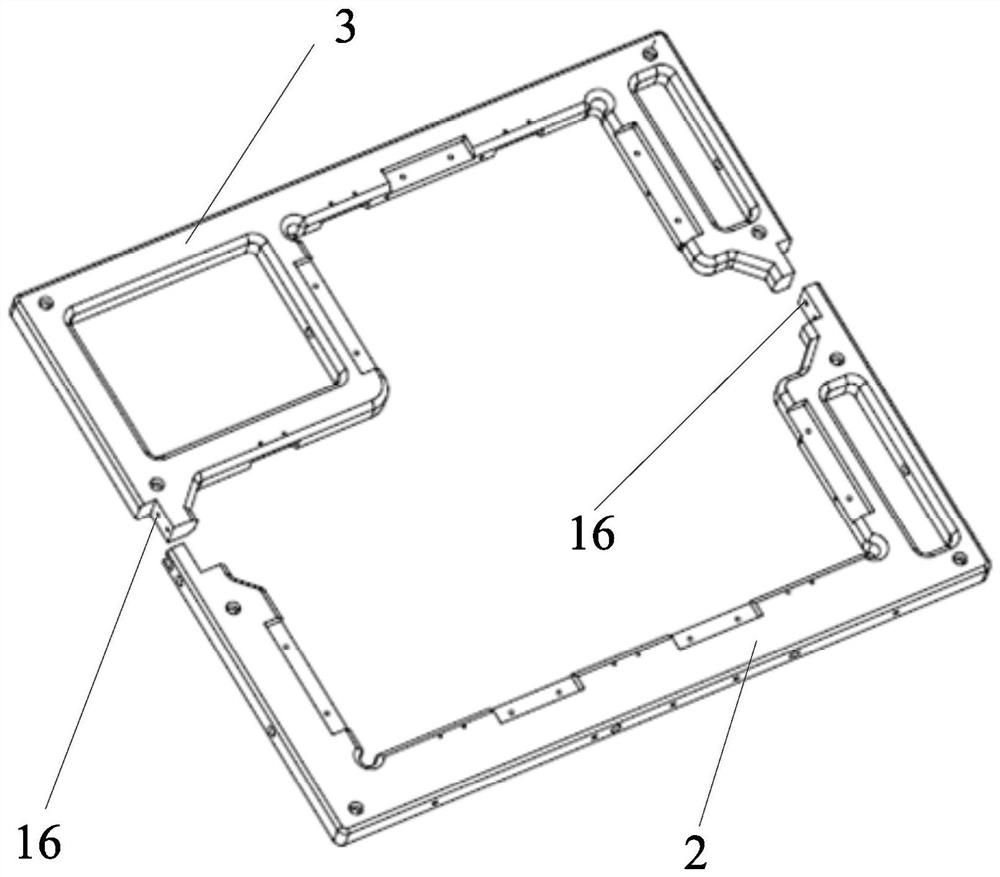
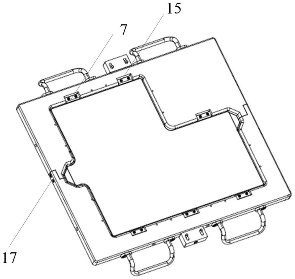
[0111] Such as figure 2 with image 3 As shown, this embodiment provides a jig tool, which includes a jig frame part 2, a jig frame two part 3 and a wedge 7, a jig frame part 2 and a jig frame two part 3 The main body of the fixture frame can be formed through assembly; the wedge 7 is detachably connected with the first part 2 of the fixture frame and the second part 3 of the fixture frame; the first part 2 of the fixture frame and the second part 3 of the fixture frame are used for The two sides opposite to the substrate 10 are attached; the main body of the fixture frame is arranged around the substrate 10; the wedge 7 is used to extend into the side wall groove of the substrate 10 during the assembly process, wherein the mating end surface 25 of the wedge is in contact with the substrate There is a gap between the mating end surfaces of the side wall groove of 10 .

[0112] The frocks in the prior art include crimp-type frocks and shrapnel-type frocks. The crimping tool...

Embodiment 2

[0122] On the basis of Example 1, as image 3 As shown, the fixture tooling also includes a wedge screw 15, and the wedge 7 is fixed on the first part 2 of the fixture frame or the second part 3 of the fixture frame through the wedge screw 15, which is beneficial to realize that the wedge 7 and the first part of the fixture frame 2 or the detachable connection of fixture frame two 3.

[0123] When the substrate 10 is made of a microcrystalline material, the wedge 7 is made of a polytetrafluoroethylene material; or, when the substrate 10 is made of a quartz material, the wedge 7 is made of an aluminum alloy material, which is conducive to better Protect the substrate 10 .

[0124] The fixture tooling also includes assembly screws 17, the fixture frame part 2 and the fixture frame two parts 3 are provided with assembly holes 16, and the assembly screws 17 can be inserted into the assembly holes 16 on the fixture frame part 2 and the fixture frame The assembly hole 16 on the se...

Embodiment 3

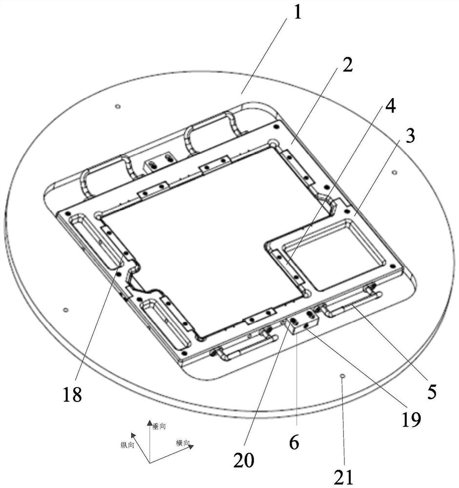
[0129] Such as Figure 7 with Figure 8 As shown, this embodiment also provides an assembly platform 8 for assembling the above-mentioned substrate assembly, the assembly platform 8 includes a support body, the top surface of the support body is provided with a support seat 9, and the end of the support seat 9 forms a limited position. Line 12, used for aligning with the edge line of substrate 10; Guide groove 11 is provided with along two longitudinal sides on the top surface of support main body, the longitudinal side of fixture frame one 2 and fixture frame two parts 3 can be positioned at Sliding in the guide groove 11, there is a gap between the groove wall of the guide groove 11 and the side walls of the longitudinal sides of the fixture frame part 2 and the fixture frame part 3.

[0130] The assembly table 8 can assist in assembling the substrate components, reduce assembly difficulty, and improve assembly accuracy.

[0131] The effect of the limit line 12 is conduciv...


PUM


Abstract

The invention provides a clamp tool, an assembling table, a substrate assembly and an assembling method and a fixing method of the substrate assembly. Wherein the clamping tool comprises a first clamping tool frame part, a second clamping tool frame part and a wedge block, and the first clamping tool frame part and the second clamping tool frame part can be assembled to form a clamping tool frame main body; the wedge block is detachably connected with the first clamp frame part and the second clamp frame part; the first clamp frame part and the second clamp frame part are used for being attached to the two opposite sides of the base plate in the assembling process. The fixture frame main body is arranged around the substrate; the wedge block is used for extending into the side wall groove of the base plate in the assembling process, and a gap is formed between the matching end face of the wedge block and the matching end face of the side wall groove of the base plate. By means of the clamping tool, zero edge of the substrate can be achieved, the contact part of the clamping tool and the surface of the substrate is prevented from being scratched due to heating, and the requirement that the clamping tool bears the substrate with large mass to move in the loading and coating process of the coating machine can be met.

Description

technical field [0001] The invention relates to the field of coating technology, in particular to a jig fixture, an assembly platform, a substrate assembly, an assembly method and a fixing method thereof. Background technique [0002] The special-shaped large-size grating substrate is used in the grating ruler measurement system of the lithography machine. The grating substrate includes a grating surface and a mounting surface. The grating is fabricated on the grating surface, and the mounting surface is fixedly connected to the grating mounting plate through optical glue. The grating face requires high precision on the edge of the grating, and some areas require zero edges. Both the grating surface and the mounting surface of the grating substrate have high precision requirements for surface type, roughness and surface quality. [0003] In the prior art, due to the large size, large mass and special shape of the special-shaped large-size grating substrate, it can only be ...

Claims


Application Information

Patent Timeline
Patent Type & Authority Applications(China)
IPC IPC(8): C23C14/50C23C14/30
CPCC23C14/50C23C14/30
Inventor 范玉娇石佩茹杨月舳孙展康帅帅
Owner BEIJING U PRECISION TECH
Why Eureka
Try Eureka