Temperature control optical module and working method thereof

A working method and technology of optical modules, applied in the field of optical communication, can solve the problems of high temperature control power consumption and low temperature control efficiency, etc.

Pending Publication Date: 2022-05-06
金雷
View PDF0 Cites 4 Cited by
  • Summary
  • Abstract
  • Description
  • Claims
  • Application Information

AI Technical Summary

Problems solved by technology

[0005] In view of this, the present invention provides a temperature control optical module and its working method to solve the problems of high temperature control power consumption and low temperature control efficiency in the prior art

Method used


Image

  • Temperature control optical module and working method thereof

Examples


Embodiment Construction

[0027] The technical solutions of the present invention will be clearly and completely described below in conjunction with the accompanying drawings. Apparently, the described embodiments are some of the embodiments of the present invention, but not all of them. Based on the embodiments of the present invention, all other embodiments obtained by persons of ordinary skill in the art without making creative efforts belong to the protection scope of the present invention.

[0028] In the description of the present invention, it should be noted that the terms "center", "upper", "lower", "left", "right", "vertical", "horizontal", "inner", "outer" etc. The indicated orientation or positional relationship is based on the orientation or positional relationship shown in the drawings, and is only for the convenience of describing the present invention and simplifying the description, rather than indicating or implying that the referred device or element must have a specific orientation, ...


PUM


Abstract

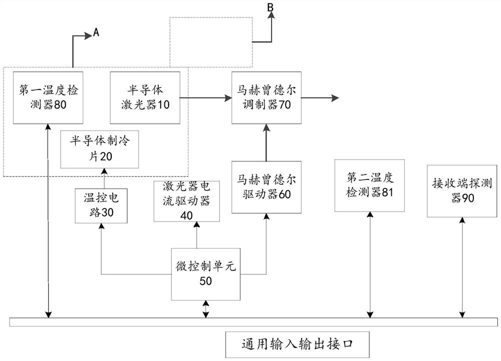
The invention discloses a temperature control optical module and a working method thereof, the temperature control optical module comprises a semiconductor laser, a laser current driver, a semiconductor chilling plate, a first temperature detector, a second temperature detector and a temperature control circuit, the first temperature detector is suitable for detecting the working temperature of the semiconductor laser, and the second temperature detector is suitable for detecting the working temperature of the semiconductor laser. The second temperature detector is suitable for detecting the temperature of the environment where the temperature control optical module is located. The temperature control circuit is suitable for carrying out current adjustment on the semiconductor chilling plate according to the detection temperature difference value of the first temperature detector and the second temperature detector so that the semiconductor laser can be cooled. And the laser current driver is suitable for carrying out current modulation on the semiconductor laser according to the detection temperature of the first temperature detector so as to heat the semiconductor laser. The temperature control optical module reduces the temperature control power consumption and improves the temperature control efficiency.

Description

technical field [0001] The invention relates to the technical field of optical communication, in particular to a temperature-controlled optical module and a working method thereof. Background technique [0002] With the advent of the 5G era, major operators are vigorously promoting the construction of 5G networks in order to seize market opportunities. The frequency of 5G networks is much faster than that of 4G networks, but the higher the frequency of the base station, the faster its attenuation will be. Therefore, the density of the base stations of the 5G network is denser than that of the 4G network. Compared with the fronthaul and backhaul of the 4G network, the 5G network also adds mid-haul on the basis of the front-haul and backhaul. The mid-haul is to better control the increasing number of front-haul base stations. Based on the consideration of cost and optical fiber resources, operators have evolved the 5G fronthaul solution from the traditional optical fiber dire...

Claims


Application Information

Patent Timeline
Patent Type & Authority Applications(China)
IPC IPC(8): H01S5/024H01S5/00
CPCH01S5/02415H01S5/02453H01S5/0014
Inventor 金雷
Owner 金雷
Why Eureka
Try Eureka