Lithium battery device with fin heat dissipation structure

A heat dissipation structure, lithium battery technology, applied in battery circuit devices, circuit devices, lithium batteries, etc., can solve problems such as liquid leakage, thermal runaway, fire and explosion

Active Publication Date: 2022-05-10
深圳市天德普储能科技有限公司
View PDF11 Cites 2 Cited by
  • Summary
  • Abstract
  • Description
  • Claims
  • Application Information

AI Technical Summary

Problems solved by technology

[0002] Lithium battery, as a kind of storage battery power supply equipment, will run out of power with the prolongation of use time. Due to the lack of intelligent monitoring equipment or means in the prior art, lithium battery can easily cause sudden power failure without the user's knowledge. , or due to long-term use, charging and discharging are not standardized, resulting in internal short circuit of the lithium battery or reduction in the life of the lithium battery, or in the case of internal hidden faults, the lithium battery continues to release too much heat during long-term use, and cannot be dissipated to the outside environment in time In the process, the internal organic material system reaches the fire temperature point, causing accidents such as fire and explosion.
Lithium batteries will fail with a certain probability during use or storage, including capacity decay (diving), short cycle life, increased internal resistance, abnormal voltage, lithium precipitation, gas production, liquid leakage, short circuit, deformation, thermal runaway, etc. , which seriously reduces the performance, consistency, reliability and safety of lithium batteries

Method used


Image

  • Lithium battery device with fin heat dissipation structure
  • Lithium battery device with fin heat dissipation structure
  • Lithium battery device with fin heat dissipation structure

Examples


Embodiment 1

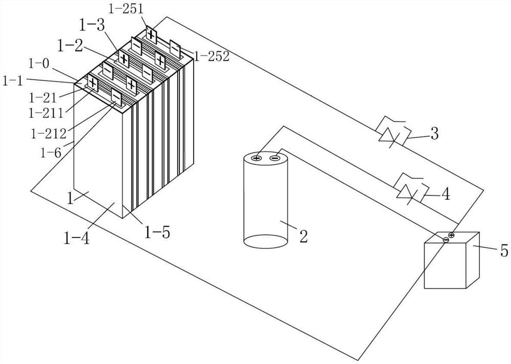
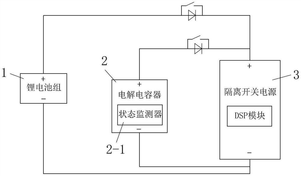
[0067] Such as figure 1 As shown, it is a lithium battery device with a finned heat dissipation structure provided in this embodiment. The device includes a lithium battery pack 1, and the device also includes an electrolytic capacitor 2 connected in parallel with the lithium battery pack 1, and a lithium battery pack connected in series with the lithium battery pack. A battery field effect transistor 3, a capacitor field effect transistor 4 connected in series with an electrolytic capacitor 2, and an isolated switching power supply 5 based on a DSP module, such as Figure 1-2 As shown, the lithium battery pack 1 includes a lithium battery pack housing 1-0, and the lithium battery pack housing 1-0 contains a single number of lithium battery slice accommodation chambers 1-1 arranged side by side from top to bottom, and each lithium battery slice accommodates Each cavity 1-1 is provided with a lithium battery sheet 1-2, and the positive and negative electrodes of multiple lithiu...

Embodiment 2

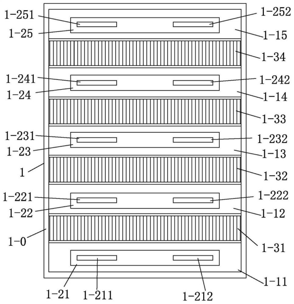
[0070] As a preferred embodiment provided by the present invention, on the basis of embodiment 1, as Figure 1-2 As shown, the number of lithium battery piece accommodation chambers is 5: the first lithium battery piece accommodation chamber 1-11, the second lithium battery piece accommodation chamber 1-12, the third lithium battery piece accommodation chamber 1-13, the fourth lithium battery piece accommodation chamber The battery piece accommodation chamber 1-14, the fifth lithium battery piece accommodation chamber 1-15, the first lithium battery piece accommodation chamber 1-11 accommodates the first lithium battery piece 1-21, the first lithium battery piece includes A first positive electrode 1-211 on the left side of a lithium battery piece accommodation chamber 1-11 and a second negative pole 1-212 on the right side, and a second lithium battery piece 1-22 is accommodated in the second lithium battery piece accommodation chamber 1-12 , the second lithium battery piece ...

Embodiment 3

[0075] On the basis of embodiment 1 or embodiment 2 or embodiment 3, as another preferred embodiment of the present invention, such as figure 1 , Image 6 As shown, each lithium battery slice accommodation chamber (the first lithium battery slice accommodation chamber 1-11 to the fifth lithium battery slice accommodation chamber 1-15) is provided with a horizontal central airflow channel on the plane 1-4 where the long side of the lithium battery slice is located. 6 and the vertical central airflow channel 7, and a plurality of V-shaped airflow channels 8 arranged at intervals from top to bottom with the vertical central airflow channel 7 as the axis of symmetry. Taking the first lithium battery chip accommodation cavity 1-11 as an example, the first A lithium battery piece accommodation cavity 1-11 is provided with a horizontal central airflow channel 6 and a vertical central airflow channel 7 perpendicular to the horizontal central airflow channel 6 on the plane 1-4 where th...


PUM


Abstract

The invention provides a lithium battery device with a fin heat dissipation structure. The lithium battery device comprises a lithium battery pack, an electrolytic capacitor connected with the lithium battery pack in parallel, a lithium battery field effect transistor connected with the lithium battery pack in series, a capacitor field effect transistor connected with the electrolytic capacitor in series, and an isolating switch power supply based on a DSP (Digital Signal Processor) module, the electrolytic capacitor is used as an auxiliary backup power supply and is in communication connection with the state monitor; the DSP module is used for controlling whether the electrolytic capacitor is started or not and controlling the working time to maintain the stable power supply of the lithium battery device; an odd number of lithium battery piece accommodating cavities which are arranged side by side are accommodated in the lithium battery pack shell; a phase change material is arranged in the lithium battery piece accommodating cavity; and fin-shaped heat dissipation plates vertical to the long edge direction of the lithium battery pieces are arranged among the plurality of lithium battery piece accommodating cavities. Aging faults of the electrolytic capacitor can be avoided, the service life of the electrolytic capacitor serving as an auxiliary power supply for maintaining stable power supply of the lithium battery device is prolonged, and uninterrupted power supply of the lithium battery pack device is guaranteed.

Description

technical field [0001] The invention belongs to the technical field of lithium battery equipment, and in particular relates to a lithium battery device with a fin heat dissipation structure. Background technique [0002] Lithium battery, as a kind of storage battery power supply equipment, will run out of power with the prolongation of use time. Due to the lack of intelligent monitoring equipment or means in the prior art, lithium battery can easily cause sudden power failure without the user's knowledge. , or due to long-term use, charging and discharging are not standardized, resulting in internal short circuit of the lithium battery or reduction in the life of the lithium battery, or in the case of internal hidden faults, the lithium battery continues to release too much heat during long-term use, and cannot be dissipated to the outside environment in time In the process, the internal organic material system reaches the fire temperature point, causing accidents such as fi...

Claims


Application Information

Patent Timeline
Patent Type & Authority Applications(China)
IPC IPC(8): H01M10/052H01M10/42H01M10/613H01M10/6551H01M10/6555H01M10/6556H01M10/6562H01M10/6569H01M50/204H01M50/224H02J7/00H02J9/06
CPCH01M10/052H01M10/613H01M10/6555H01M10/6551H01M10/6569H01M10/6562H01M10/6556H01M50/204H01M50/224H01M10/4285H02J9/068H02J7/0047H02J7/0063Y02E60/10
Inventor 谢传建
Owner 深圳市天德普储能科技有限公司
Why Eureka
Try Eureka