
Biomass energy raw material treatment device

A raw material processing, biomass energy technology, applied in grain processing, chemical/physical process, transportation and packaging, etc., can solve problems affecting energy conversion rate, etc., to achieve the effect of enhancing the effect of crushing and stirring

Pending Publication Date: 2022-05-13
李盛贤
View PDF6 Cites 2 Cited by
  • Summary
  • Abstract
  • Description
  • Claims
  • Application Information

AI Technical Summary

Problems solved by technology

This biomass energy raw material processing equipment achieves the purpose of using clean energy and feeding safety, but this kind of biomass energy raw material processing equipment mainly performs stamping processing through pressing parts, and the stamping effect is not as obvious as the way of high rotation and crushing, so that Affect the energy conversion rate

Method used


Image

  • Biomass energy raw material treatment device
  • Biomass energy raw material treatment device
  • Biomass energy raw material treatment device

Examples


Embodiment 1

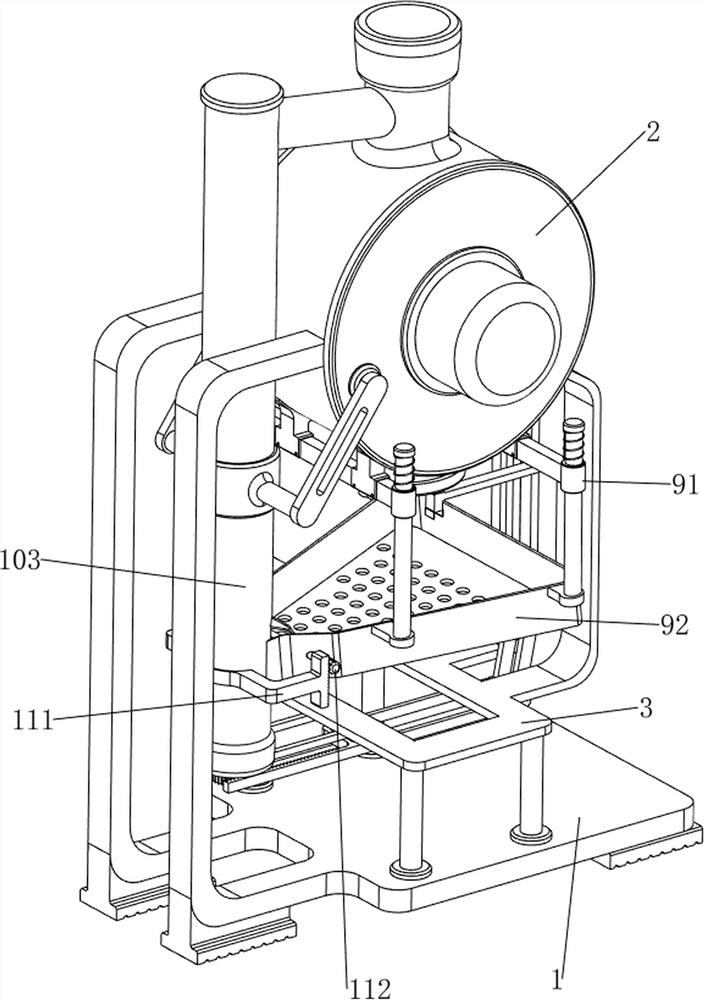
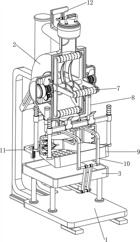
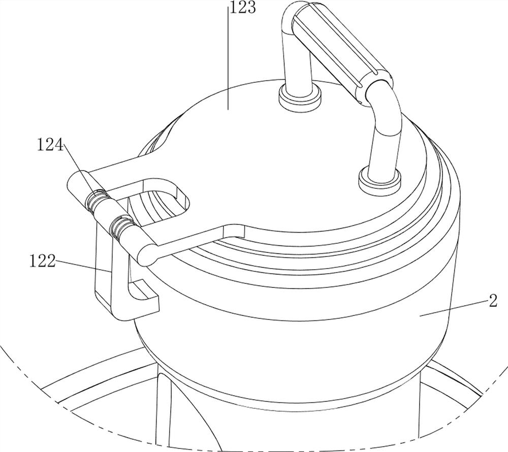
[0038] A biomass energy raw material processing device, such as figure 1 , figure 2 with image 3As shown, it includes a first support 1, a stirring frame 2, a second support 3, a drive motor 4, a rotating shaft 5, a cutter 6, a crushing mechanism 7 and a cutting mechanism 8, and the upper part of the first support 1 is fixed by means of A stirring frame 2 is provided, and the top and bottom of the stirring frame 2 are respectively provided with a feed inlet and a discharge port. A drive motor 4 is installed on the front side of the material frame 2 through bolts, and a rotating shaft 5 is connected between the output shaft of the drive motor 4 and the inner rear part of the material stirring frame 2. The middle part is provided with two cutters 6 by means of a key connection, and the cutters 6 are set as blades, a crushing mechanism 7 is provided between the stirring frame 2 and the rotating shaft 5, and a material cutting mechanism 8 is provided at the bottom of the stirr...

Embodiment 2

[0043] On the basis of Example 1, such as figure 1 , Figure 8 with Figure 9 As shown, a screening mechanism 9 is also included, and the screening mechanism 9 includes a second sliding sleeve 91, a material receiving frame 92, a compression spring 93, a moving block 94, a fourth support 95, a shifting block 96 and a second torsion spring 97, stirring The left and right sides of the bottom of the material frame 2 are welded and connected with a second sliding sleeve 91, and a material receiving frame 92 is slidably arranged between the second sliding sleeves 91. The bottom of the material receiving frame 92 is uniformly provided with sieve holes, and the second sliding sleeve 91 tops are all wound with compression spring 93, and compression spring 93 two ends are respectively connected with second sliding sleeve 91 and material receiving frame 92, and supporting frame 84 outer ends are all provided with moving block 94, and material receiving frame 92 bottom, front and rear b...


PUM


Abstract

The invention relates to a raw material treatment device, in particular to a biomass energy raw material treatment device. The invention provides the biomass energy raw material treatment device which can be used for highly rotating and crushing biomass energy raw materials so as to improve the energy conversion rate. A biomass energy raw material processing device comprises a first support, a material stirring frame, a second support, a driving motor, a rotating shaft, a cutter, a grinding mechanism and the like, the material stirring frame is arranged on the upper portion of the first support, the second support is connected between the lower right portion of the material stirring frame and the lower portion of the first support, and the driving motor is installed on the front side in the material stirring frame; a rotating shaft is connected between an output shaft of the driving motor and the rear part in the stirring frame, the rotating shaft is rotatably connected with the stirring frame, two cutters are arranged in the middle of the rotating shaft, and a crushing mechanism is arranged between the stirring frame and the rotating shaft. The cutter is used for crushing biomass energy raw materials, the rolling roller is used for stirring the biomass energy raw materials, and the rotating directions of the rolling roller and the cutter are opposite, so that the crushing and stirring effects are enhanced.

Description

technical field [0001] The invention relates to a raw material processing device, in particular to a biomass energy raw material processing device. Background technique [0002] Biomass energy is a kind of renewable energy that uses biomass as the medium and carrier to store solar energy. It conforms to the theme of green environmental protection. Biomass refers to various organisms produced through photosynthesis. These organisms are processed and then fermented Converted into chemical energy and stored in biomass, the solar energy can be fully utilized, low pollution, and renewable. [0003] Patent application CN208359542U discloses a biomass energy raw material processing equipment, including a body, the bottom of the body is fixedly connected with a pressure plate, the top of the pressure plate is provided with a pressing groove, and the bottom of the pressure plate is A base is fixedly connected, the front of the base is fixedly connected with a control area, the front...

Claims


Application Information

Patent Timeline
Patent Type & Authority Applications(China)
IPC IPC(8): B02C18/14B01F33/83B02C18/16B02C18/22B02C18/24B02C23/12B07B1/28B07B1/42
CPCB02C18/14B02C18/24B02C18/2216B02C23/12B07B1/28B07B1/42B02C18/16B02C2018/164Y02E50/30
Inventor 李盛贤
Owner 李盛贤
Learn More