Automatic cutting equipment for mechanical engineering

A cutting equipment and mechanical engineering technology, applied in the field of automatic cutting equipment for mechanical engineering, can solve the problems of poor working environment, scattered waste, waste collection and cleaning, etc., to improve cutting quality, reduce labor intensity, and improve practicality. sexual effect

Pending Publication Date: 2022-05-13
潘虎
View PDF12 Cites 1 Cited by
  • Summary
  • Abstract
  • Description
  • Claims
  • Application Information

AI Technical Summary

Problems solved by technology

The traditional cutting method is to fix the cutting piece on the fixture, and then cut the cutting piece by manually operating the cutting machine, which not only increases the labor load of the workers, but also has deviations in the cutting accuracy, which reduces the efficiency of the cutting work; among them, the steel pipe has Hollow section, the length of which is much longer than the diameter or circumference of steel, steel pipes can not only be used to transport fluid and powdery solids, exchange heat, manufacture mechanical parts and containers, but also be used to manufacture building structure grids, pillars and mechanical supports, It can further reduce the weight of the device and is widely used in production and life. In actual use, it is necessary to cut the steel pipe first; in addition, the traditional cutting method cannot collect and clean up the waste generated by cutting, causing the waste to scatter. Make the working environment of workers worse and affect the health of workers

Method used


Image

  • Automatic cutting equipment for mechanical engineering
  • Automatic cutting equipment for mechanical engineering
  • Automatic cutting equipment for mechanical engineering

Examples


Embodiment Construction

[0030] The following will clearly and completely describe the technical solutions in the embodiments of the present invention with reference to the accompanying drawings in the embodiments of the present invention. Obviously, the described embodiments are only part of the embodiments of the present invention, not all of them. Based on the embodiments of the present invention, all other embodiments obtained by persons of ordinary skill in the art without creative efforts fall within the protection scope of the present invention.

[0031] It should be noted that if there are directional indications (such as up, down, left, right, front, back...) in the embodiment of the present invention, the directional indications are only used to explain how to move in a certain posture (as shown in the accompanying drawings). If the specific posture changes, the directional indication will also change accordingly.

[0032] In addition, if there are descriptions involving "first", "second" an...


PUM


Abstract

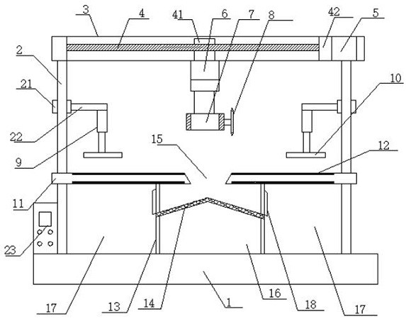
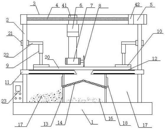
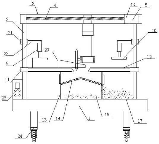
The invention belongs to the technical field of cutting equipment, and discloses automatic cutting equipment for mechanical engineering, which comprises a machine base, a screw rod, a hydraulic driving rod, a cutting motor, a clamping pressing plate, a cutting worktable, a conveying belt and a fine scrap collecting tank, a cutting workbench is supported and mounted above the machine base through a machine column, a machine cross frame is fixedly mounted at the top end of the machine column, and a fine scrap collecting groove and a coarse scrap collecting groove are formed below the cutting workbench through a supporting plate; a lead screw is installed in the machine cross frame, and a lead screw motor in driving connection with the lead screw is installed at one end of the machine cross frame. The hydraulic driving rod is arranged on the lead screw through a lead screw sliding seat, and a cutting motor is mounted at the bottom end of the hydraulic driving rod through a motor mounting seat. The conveying belt conveys to-be-cut accessories, the clamping and pressing plate is fixed, the electric control box controls the cutting height and position adjustment in order, automatic cutting is achieved, and the cutting quality is improved; and the labor intensity of workers is relieved, the working environment is improved, and the effect of effectively collecting and cleaning sweeps is achieved.

Description

technical field [0001] The invention relates to the technical field of cutting equipment, in particular to an automatic cutting equipment for mechanical engineering. Background technique [0002] Mechanical engineering is an engineering discipline that involves the application of the laws of physics for the analysis, design, manufacture and maintenance of mechanical systems. Cutting is a physical action. Cutting in a narrow sense refers to cutting objects (such as food, wood and other objects with low hardness) with sharp tools such as knives; cutting in a broad sense refers to using tools, such as machine tools, flames, etc. down to disconnect. Cutting plays an important role in people's production and life. [0003] The general cutting device has the problem that the cutting depth is not easy to adjust, and it cannot be automatically driven to cut the article during use, and the waste after cutting is not easy to deal with. Therefore, we propose a more practical machine...

Claims


Application Information

Patent Timeline
Patent Type & Authority Applications(China)
IPC IPC(8): B23D33/02B23D21/00B23Q7/00B23Q1/44B23Q5/10B23Q5/26B23Q11/00B07B1/04
CPCB23D33/02B23D21/00B23Q7/003B23Q1/44B23Q5/10B23Q5/26B23Q11/0042B07B1/04
Inventor 潘虎
Owner 潘虎
Why Eureka
Try Eureka