
Method of forming a semiconductor device

A semiconductor and device technology, which is applied in the field of semiconductor device formation, can solve the problems of limited improvement effect, increase the difficulty of chemical mechanical polishing of copper, and high cost, so as to optimize the high and low fluctuation state, improve copper butterfly defects, and prolong the service life Effect

Active Publication Date: 2022-07-01
NEXCHIP SEMICON CO LTD
View PDF17 Cites 0 Cited by
  • Summary
  • Abstract
  • Description
  • Claims
  • Application Information

AI Technical Summary

Problems solved by technology

[0003] Because electroplating copper is affected by the pattern, there is usually obvious overplating phenomenon in the area with small line width and high pattern density, and there are great differences in the height and fluctuation of the copper film, which often increases the difficulty of copper chemical mechanical polishing (CMP)
In order to achieve the purpose of comprehensive planarization, copper residues will appear in areas with high pattern density, which will easily lead to short circuit of metal lines
In order to solve the problem of copper residue, after grinding, copper butterfly-shaped depressions will appear in large open areas, which will cause the next layer of metal wires to break
[0004] For the overplating phenomenon, the current way to improve it is to use more advanced organic additives at a high cost, but the improvement effect is limited, especially for high-density pattern areas.

Method used


Image

  • Method of forming a semiconductor device
  • Method of forming a semiconductor device
  • Method of forming a semiconductor device

Examples


Embodiment Construction

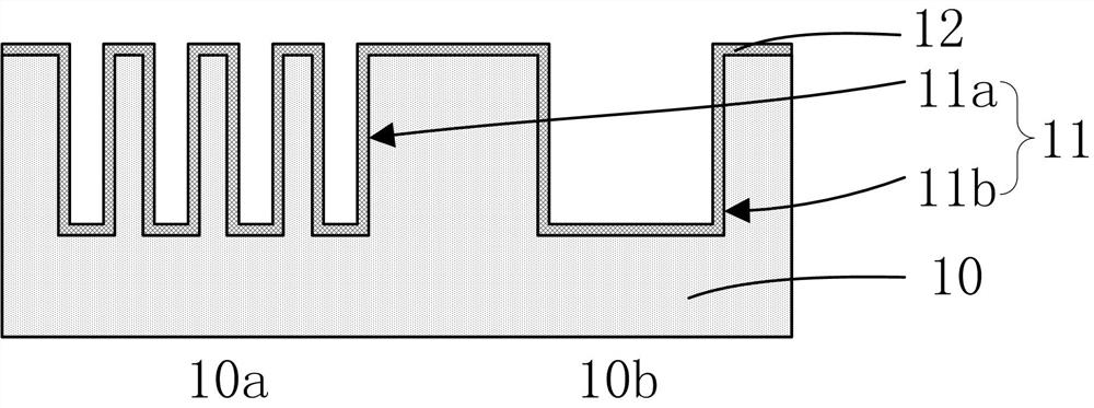
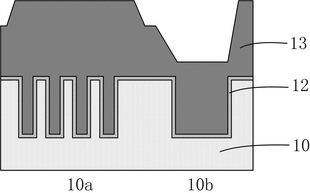
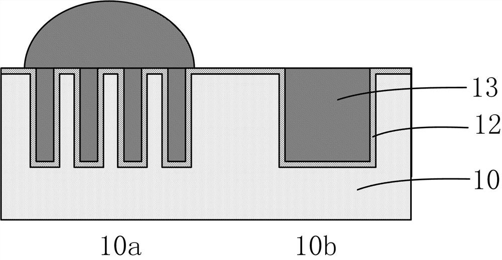
[0035] figure 1 is a schematic diagram of the structure after the grooves are formed on the substrate, figure 2 It is a schematic diagram of the structure after electroplating copper in the groove, image 3 is a schematic diagram of the structure after the copper is planarized, Figure 4 It is a schematic diagram of the structure after the copper has been ground. Please refer to figure 1 As shown, a substrate (not shown) is provided on which a dielectric layer 10 is formed, the dielectric layer 10 including high-density patterned regions 10a and low-density patterned regions 10b. Grooves 11 are formed in the dielectric layer 10. The grooves 11 include a first groove 11a located in the high-density pattern area 10a and a second groove 11b located in the low-density pattern area 10b. The cross-sectional width of the groove 11b is larger than the cross-sectional width of the first groove 11a. Next, a copper seed layer 12 is formed, and the copper seed layer 12 covers the si...


PUM


Abstract

The present invention provides a method for forming a semiconductor device. In the method, copper deposition includes a step of depositing the bottom of the groove, a step of filling the groove to fill at least the first groove, and a step of planar deposition, and the step of filling the groove Compared to the deposition step at the bottom of the groove, the concentration of the accelerator is reduced and the concentration of the inhibitor is increased. In the present invention, when the deposition step at the bottom of the groove is performed, the copper deposition at the bottom of the groove is quickly completed by using an accelerator, and when the filling step of the groove is performed subsequently, the concentration of the accelerator decreases and the concentration of the inhibitor increases, so as to reduce the amount of the groove. The filling speed can avoid the problem of over-plating caused by the rapid filling of the groove, and can reduce the convex height of the surface after the groove is filled. Follow-up deposition steps can further reduce the thickness difference of electroplating copper in different areas, thereby improving the appearance of chemical mechanical polishing. copper residues and copper butterfly defects, improve product reliability and prolong product life.

Description

technical field [0001] The present invention relates to the technical field of integrated circuit manufacturing, in particular to a method for forming a semiconductor device. Background technique [0002] In the semiconductor manufacturing process, a copper electroplating process is usually used for interconnection, that is, a groove is formed first, and then copper is electroplated in the groove. The copper electroplating process fills the grooves with the bottom up growing. Due to the use of accelerators, the growth rate at the bottom of the grooves is greater than that at the sidewalls and openings. When the grooves are filled, copper will continue to rush up and grow. The copper thickness of the final groove area is higher than that of the open area, and the phenomenon of over-plating occurs. With the advancement of the process node, the line width gradually shrinks, and the over-plating phenomenon becomes more and more obvious. [0003] Since copper electroplating is ...

Claims


Application Information

Patent Timeline
Patent Type & Authority Patents(China)
IPC IPC(8): H01L21/8238
CPCH01L21/823878H01L21/823821
Inventor 周丹玫胡万春王松
Owner NEXCHIP SEMICON CO LTD
Learn More