Cooling module for electric energy storage unit group and electric energy management system thereof
A technology for electric energy storage and cooling modules, which is applied in the direction of electric energy storage systems, electrical components, battery circuit devices, etc., and can solve the problem of affecting the service life and normal working state of electric energy storage units, the inability to quickly assemble and disassemble electric energy storage units, and poor cooling effect and other problems, to achieve the effect of improving the cooling effect, fast loading and unloading, and fast cooling speed
- Summary
- Abstract
- Description
- Claims
- Application Information
AI Technical Summary
Problems solved by technology
Method used
Image

Examples
Embodiment 1
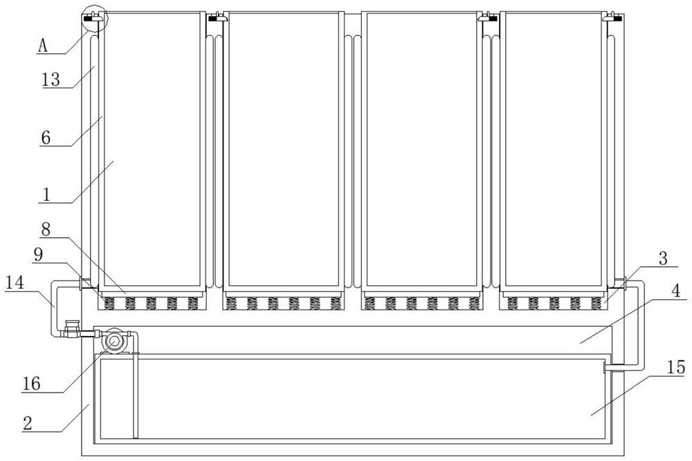
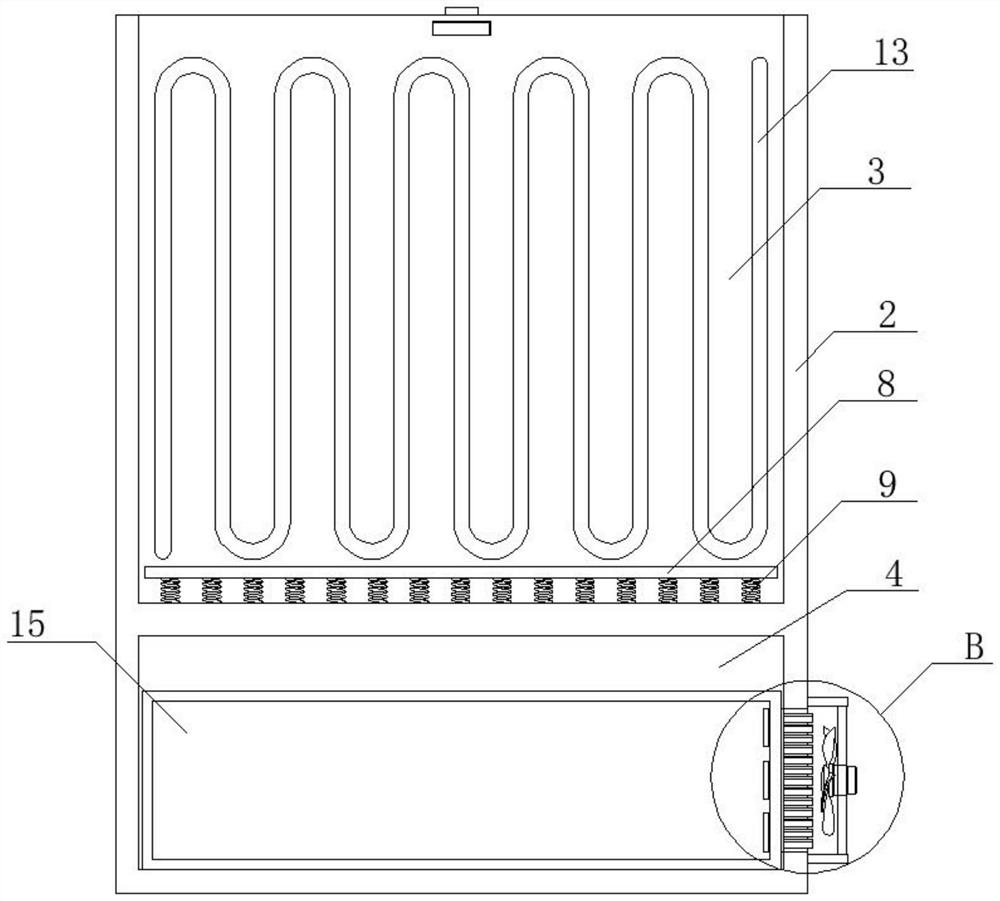
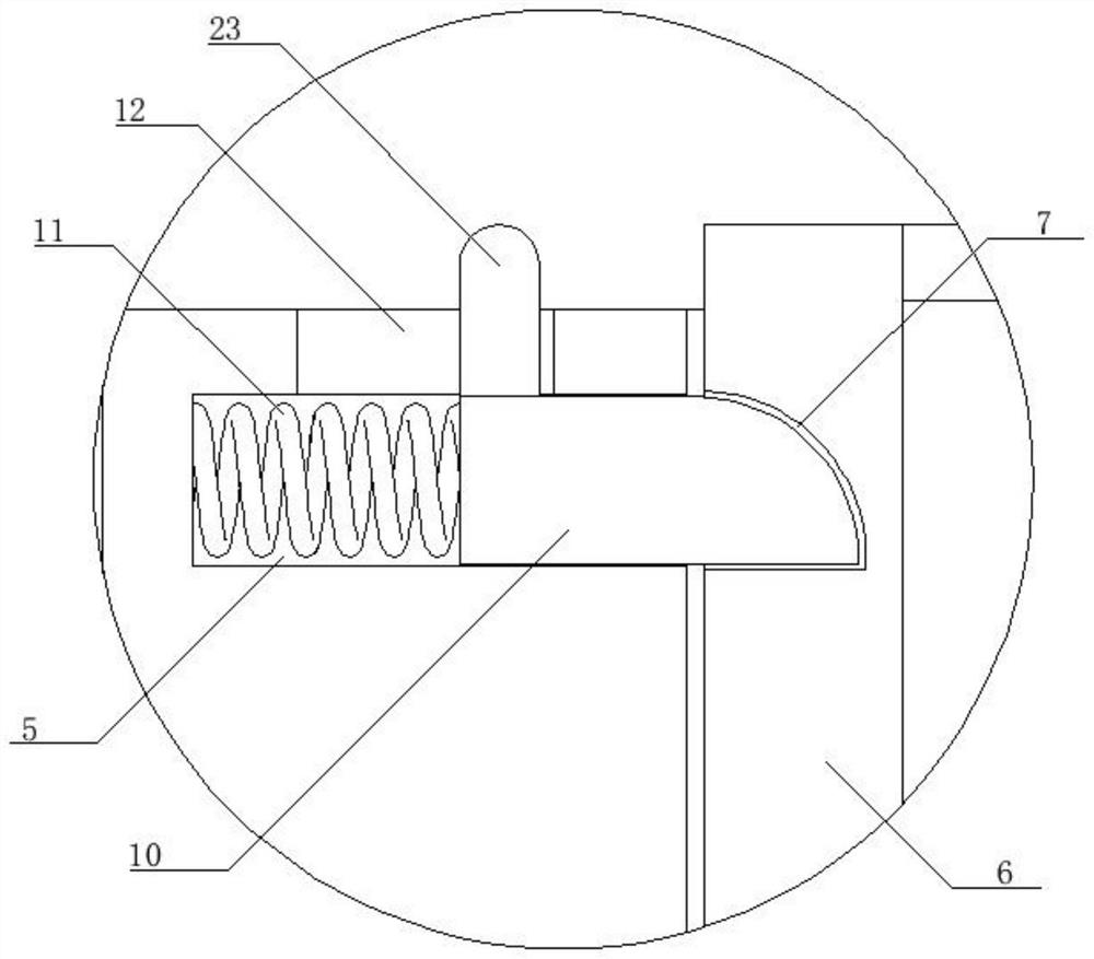
[0032] A cooling module for an electric energy storage unit group, including a plurality of electric energy storage units 1, characterized in that it also includes a casing 2, the surface of the casing 2 is provided with a cooling chamber 4 and a plurality of battery installation grooves 3, and the electric energy storage unit 1 It is detachably and fixedly connected in the battery setting groove 3, and the bottom of the battery setting groove 3 is provided with a battery pop-up assembly, and the upper side wall of the battery setting groove 3 is provided with an accommodating groove 5, and the accommodating groove 5 is provided with a fixed assembly, and the electric energy The outside of the storage unit 1 is fixedly connected with a fixed frame 6, the side wall of the fixed frame 6 is provided with a fixed slot 7 matching with the fixed assembly, the inner walls of both sides of the battery installation slot 3 are fixedly connected with a water cooling assembly, and the water...
Embodiment 2
[0039] The power management system for the electric energy storage unit group, including the main board, the main board is connected with the slave board, BDU and high-voltage control board, the main board communicates with each slave board through CAN, and the unit voltage and unit temperature of the power storage unit 1 from the slave board, BDU Including pre-charging circuit, total positive relay, total negative relay and fast charging relay, high-voltage control board includes electric energy storage unit group voltage and current detection module, pre-charge detection module and insulation detection module.
Embodiment 3
[0041] A cooling module for an electric energy storage unit group, specifically including the following operation methods:
[0042] Step 1, install the electric energy storage unit 1, put each electric energy storage unit 1 into the battery setting groove 3, when the electric energy storage unit 1 enters the battery setting groove 3, the compression spring 11 drives the fixing block 10 into the fixing groove 7 The electric energy storage unit 1 is fixed;
[0043] Step 2, when the electric energy storage unit 1 is working, the booster pump 16 starts to pump the coolant in the water-cooled tank 15 into the liquid guide pipe 14, and the liquid guide pipe 14 makes the coolant circulate in each water-cooled pipe 13, and the coolant passes through The water-cooled pipe 13 cools the electric energy storage unit 1 and then flows back into the water-cooled box 15;
[0044] Step 3, the refrigeration element is powered on and started, the refrigeration plate 17 absorbs heat to cool the ...
PUM
 Abstract
Description
Claims
Application Information
 - R&D
- Intellectual Property
- Life Sciences
- Materials
- Tech Scout
- Unparalleled Data Quality
- Higher Quality Content
- 60% Fewer Hallucinations
Browse by: Latest US Patents, China's latest patents, Technical Efficacy Thesaurus, Application Domain, Technology Topic, Popular Technical Reports.
© 2025 PatSnap. All rights reserved.Legal|Privacy policy|Modern Slavery Act Transparency Statement|Sitemap|About US| Contact US: help@patsnap.com