
Battery pack vacuum liquid injection device and method

A technology of vacuum liquid injection device and battery pack, which is applied in the direction of battery pack components, electrolyte storage battery manufacturing, non-aqueous electrolyte storage battery, etc. It can solve the problems of high hardware cost, many valves in the liquid injection cup, and poor product absorption consistency. To achieve the effect of improving process efficiency and novel design

Active Publication Date: 2022-05-13
SHENZHEN BROTHERS AUTOMATION TECH CO LTD
View PDF9 Cites 1 Cited by
  • Summary
  • Abstract
  • Description
  • Claims
  • Application Information

AI Technical Summary

Problems solved by technology

[0003] In the existing liquid injection technology, the battery and the liquid injection cup are generally evacuated first, and after the vacuum is completed, the lower liquid port of the liquid injection cup is blocked, and then the liquid injection cup is ventilated to the atmosphere so that the cup is in a normal pressure state, and then the The electrolyte is poured into the liquid injection cup. After the injection is completed, the liquid injection port is opened. At this time, the battery is in a vacuum state. The liquid injection cup body is in a normal pressure state to form a differential pressure liquid; in this liquid injection mode, vacuum first After the liquid injection, the overall equipment capacity is low and the hardware cost is high; the battery and the cup need to be vacuumed, the vacuuming volume is large, the energy consumption is high, and the time is long; there are many valves in the liquid injection cup, which affects the vacuum degree of the battery and makes it difficult to reach the ultimate vacuum. Ultimately resulting in poor product absorption consistency

Method used


Image

  • Battery pack vacuum liquid injection device and method
  • Battery pack vacuum liquid injection device and method
  • Battery pack vacuum liquid injection device and method

Examples


Embodiment Construction

[0034] The following will clearly and completely describe the technical solutions in the embodiments of the present invention with reference to the accompanying drawings in the embodiments of the present invention. Obviously, the described embodiments are only some of the embodiments of the present invention, not all of them. Based on the embodiments of the present invention, all other embodiments obtained by persons of ordinary skill in the art without making creative efforts belong to the protection scope of the present invention.

[0035] In addition, an element in the present invention is said to be "fixed" or "disposed on" another element, and it may be directly on another element or an intervening element may also exist. When an element is referred to as being "connected to" another element, it can be directly connected to the other element or intervening elements may also be present. The terms "vertical," "horizontal," "left," "right," and similar expressions are used h...


PUM


Abstract

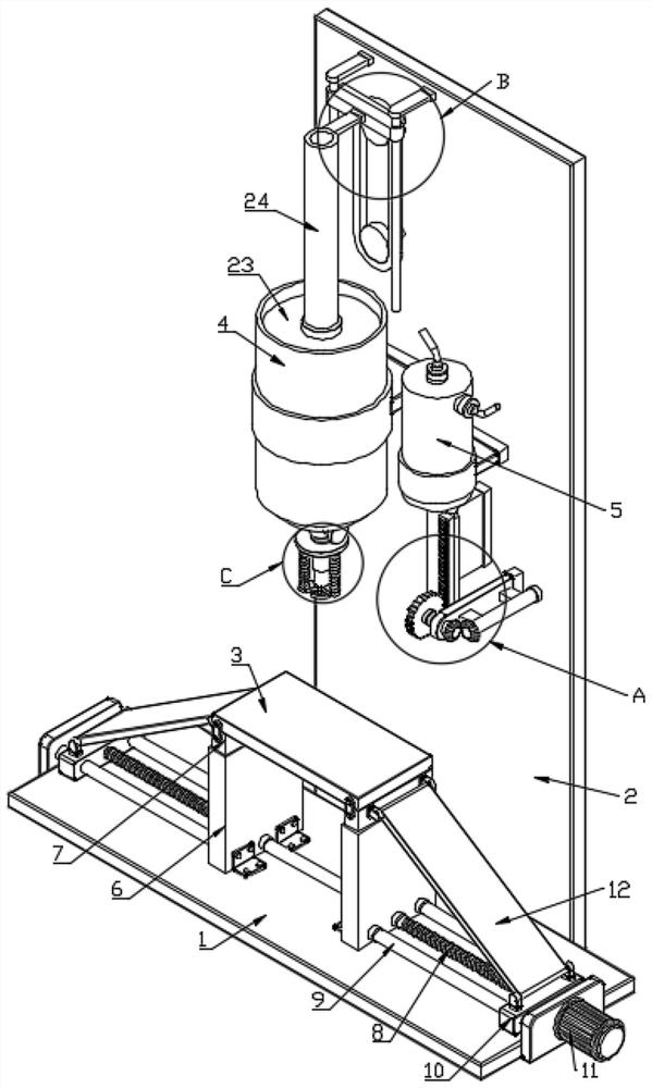
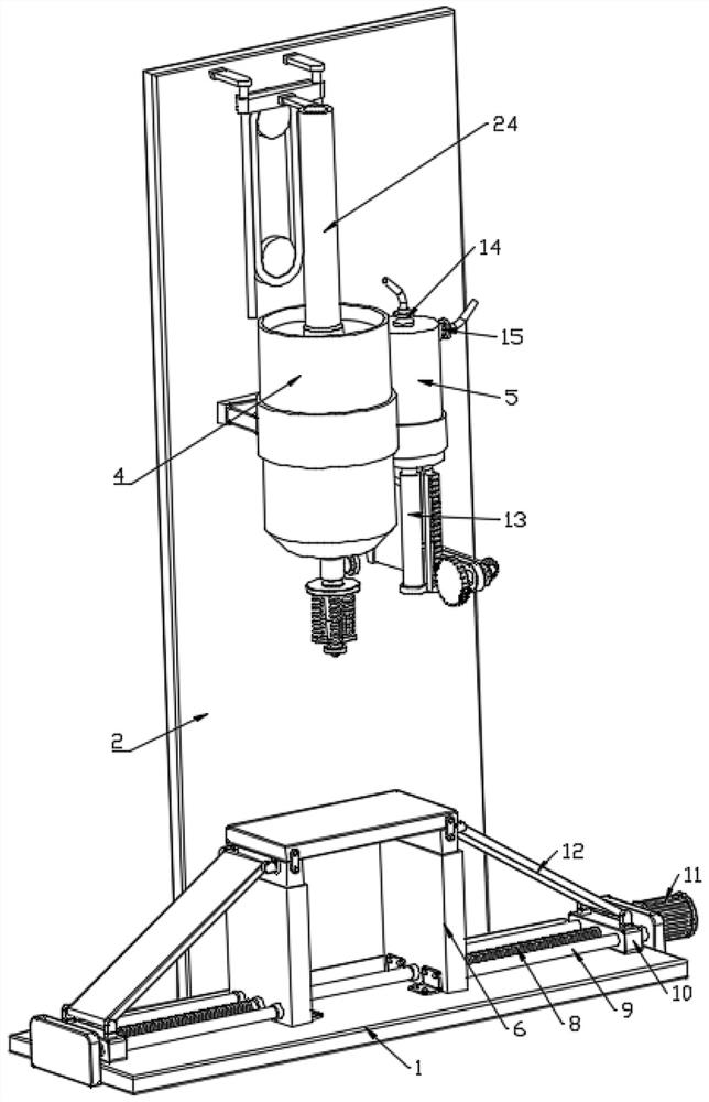
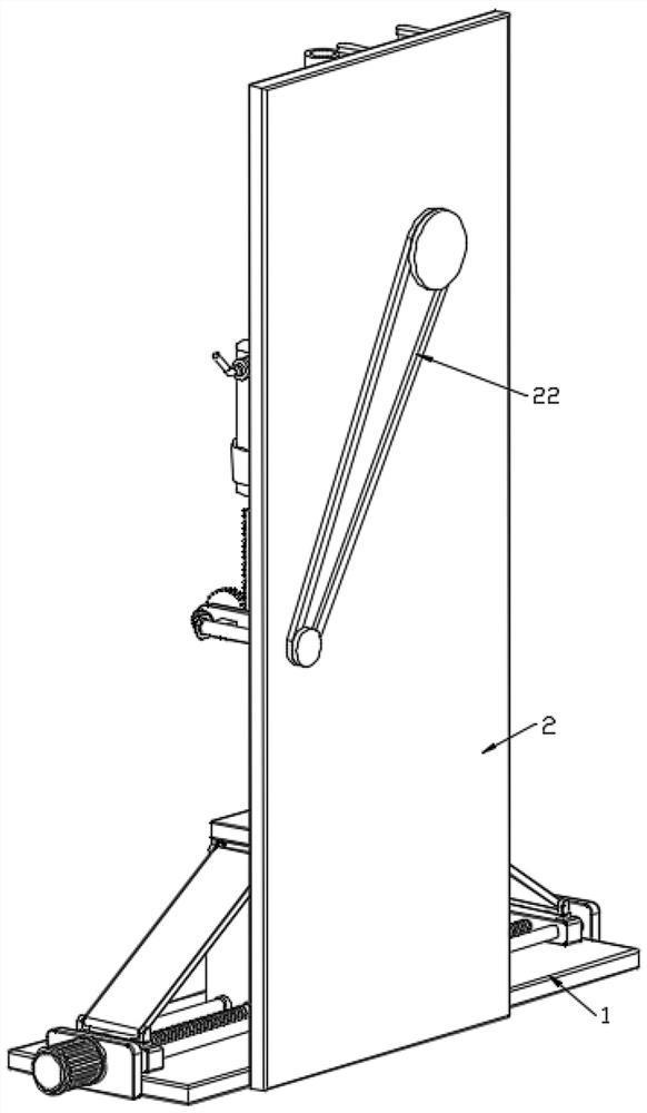
The invention relates to a battery pack vacuum liquid injection device and method.The battery pack vacuum liquid injection device comprises a base, a vertical plate and a transverse plate, the vertical plate is fixedly installed on the side portion of the base and is perpendicular to the base, the transverse plate is movably arranged on the base through a thread lifting mechanism and is parallel to the base, and the transverse plate is used for containing a battery; a liquid supply cylinder and an air suction cylinder are fixedly installed on the side, facing the transverse plate, of the vertical plate, the liquid supply cylinder is used for containing electrolyte, an exhaust mechanism is installed on the liquid supply cylinder, and when liquid injection is conducted on the battery, a bottom outlet of the liquid supply cylinder is connected with the battery through an elastic sealing mechanism; an air pumping mechanism for vacuumizing the battery is mounted on the air pumping cylinder, and the air pumping mechanism is connected with the air exhausting mechanism through a one-way transmission mechanism, so that finally, the synchronism of vacuumizing and liquid injection is realized, only the battery is vacuumized, and the process efficiency, the battery vacuum degree, the liquid injection absorptivity, the product consistency and the quality are improved.

Description

technical field [0001] The invention relates to the technical field related to battery production and processing, in particular to a vacuum liquid injection device and method for a battery pack. Background technique [0002] Polymer lithium-ion batteries generally include a battery case and an electric core and an electrolyte contained in the battery case. The electric core includes a positive pole, a negative pole, and a separator between the positive pole and the negative pole; The negative electrodes play the role of conducting electrons, and serve as the lithium ion current transmission medium in the process of charging and discharging the battery, which is the guarantee for the polymer lithium ion battery to obtain the advantages of high voltage and high specific energy. Therefore, in the production process of polymer lithium-ion batteries, liquid injection is a very important process operation. [0003] In the existing liquid injection technology, the battery and the ...

Claims


Application Information

Patent Timeline
Patent Type & Authority Applications(China)
IPC IPC(8): H01M50/609H01M10/058
CPCH01M50/609H01M10/058Y02P70/50
Inventor 袁维万克存李月生
Owner SHENZHEN BROTHERS AUTOMATION TECH CO LTD
Learn More