Steady-flow heat storage type hydraulic control compressed air energy storage system and method based on clean energy

A compressed air energy storage and clean energy technology, applied in the field of energy storage and clean energy utilization, can solve the problems of low power generation efficiency of steam turbines, affecting system safety, waste of compressed air heat, etc., to enhance energy utilization efficiency and improve safety and stability, enhanced heat transfer effect

Pending Publication Date: 2022-05-13
POWERCHINA HUADONG ENG COPORATION LTD
View PDF0 Cites 2 Cited by
  • Summary
  • Abstract
  • Description
  • Claims
  • Application Information

AI Technical Summary

Problems solved by technology

However, wind energy and solar energy have the characteristics of volatility and intermittency, so the direct power generation of wind energy and solar energy has the problem of current instability, and its direct input into the compressed air energy storage system will cause unstable operation of the system and affect the safety of the system
In addition, compressed air energy storage technology also has problems such as the waste of compressed air heat and the low efficiency of steam turbine power generation, which need to be solved

Method used


Image

  • Steady-flow heat storage type hydraulic control compressed air energy storage system and method based on clean energy
  • Steady-flow heat storage type hydraulic control compressed air energy storage system and method based on clean energy
  • Steady-flow heat storage type hydraulic control compressed air energy storage system and method based on clean energy

Examples


Embodiment Construction

[0041] The present invention is described in further detail with reference to the accompanying drawings and specific embodiments.

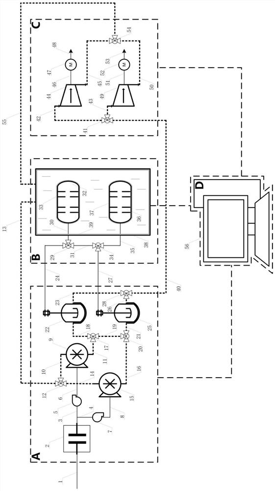
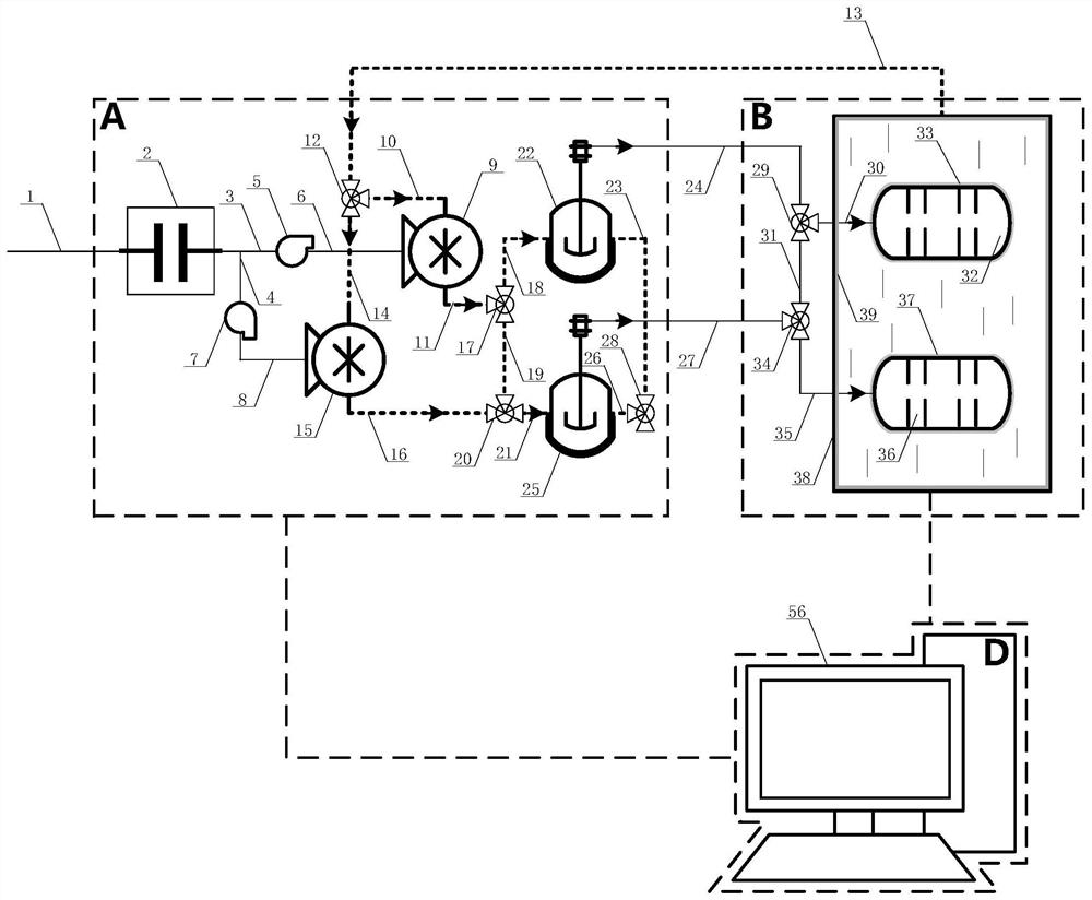
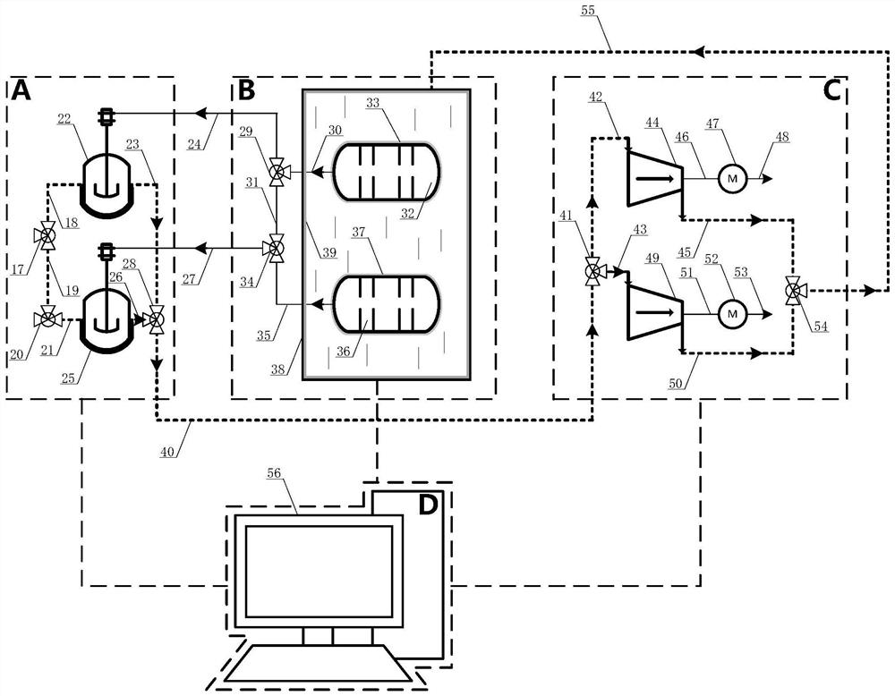
[0042] Such as figure 1 As shown, a steady-flow heat-storage liquid-controlled compressed air energy storage system based on clean energy includes a steady-flow pumping system A, a compressed heat-storage gas storage system B, a water-pushing power generation system C, and an integrated control system D.

[0043] Steady flow pumping system A modulates the frequency of the fluctuating current generated by clean energy such as wind energy and solar energy, and outputs a stable current to drive the water pump to compress the air.

[0044] Compressed heat storage and gas storage system B stores the compressed air and the heat released during the process of compressing the air.

[0045] The hydraulic power generation system C utilizes the exhaust of compressed air to drive a water turbine to generate electricity.

[0046] The integrated control syste...


PUM


Abstract

The invention provides a steady-flow heat storage type hydraulic control compressed air energy storage system and method based on clean energy. The system comprises a steady-flow water pumping system, a compression heat storage and gas storage system, a water pushing power generation system and a comprehensive control system. The super capacitor in the steady-flow water pumping system is used for carrying out frequency modulation on fluctuation current generated by clean energy such as wind energy and solar energy, and stable current is output to drive a water pump to pump water to compress air; compressed air is stored through an air storage tank in the compression heat storage and air storage system, waste heat of circulating water is recycled through a water storage tank, and heat transfer between the air storage tank and the water storage tank is regulated and controlled through a heat switch formed by a light sensation material pattern layer and a light strip. The power generation system utilizes exhaust of compressed air to push a water turbine to generate power, heat storage capacity of a water storage tank is transmitted to the compressed air, and pressure intensity and temperature losses during exhaust of an air storage tank are made up. And the comprehensive control system is used for remotely monitoring and regulating the steady flow pumping system, the compression heat and gas storage system and the water pushing power generation system.

Description

technical field [0001] The invention belongs to the technical field of energy storage and clean energy utilization, and in particular relates to a steady flow heat storage type liquid-controlled compressed air energy storage system and method based on clean energy. Background technique [0002] Electric energy storage systems can be divided into mechanical energy storage (pumped water storage, compressed air energy storage, flywheel energy storage), electromagnetic energy storage and electrochemical energy storage according to technology. Pumped hydro storage, compressed air energy storage, and electrochemical energy storage are currently considered large-scale electric energy storage technologies. However, pumped hydro storage is vulnerable to geographical conditions and environmental constraints; battery energy storage has short life, environmental pollution and safety issues. Compressed air energy storage is regarded as the most promising physical energy storage technolo...

Claims


Application Information

Patent Timeline
Patent Type & Authority Applications(China)
IPC IPC(8): H02J15/00H02J3/28H02J7/00F03B13/00F04B41/02
CPCH02J15/00H02J15/006H02J3/28H02J7/0068F03B13/00F04B41/02F05B2220/706H02J2207/50
Inventor 冯飙许志翔赵源徐晨轩李成军郑应霞张宝勇黄靖乾周杰陈顺义
Owner POWERCHINA HUADONG ENG COPORATION LTD
Why Eureka
Try Eureka