
Method for realizing integrated machining of special-shaped deep small hole with thermal barrier coating by restraining liquid light transmission through dry ice

A processing method and technology of deep and small holes, applied in the direction of metal processing equipment, electric processing equipment, manufacturing tools, etc., can solve the problems of complicated process, delamination of thermal barrier coating and metal substrate, etc., so as to improve stability and avoid fluid Divergence instability, the effect of improving processing efficiency and quality

Active Publication Date: 2022-05-17
JIANGSU UNIV
View PDF9 Cites 2 Cited by
  • Summary
  • Abstract
  • Description
  • Claims
  • Application Information

AI Technical Summary

Problems solved by technology

However, this combined processing method requires the machine tool spindle to have extremely high movement accuracy and positioning accuracy. The electrolytic machining of deep and small holes can only be carried out after the position of the special-shaped hole after laser processing is accurately positioned, and the process is relatively complicated.
In addition, laser scanning processing of special-shaped holes with thermal barrier coatings can easily lead to delamination of thermal barrier coatings and metal substrates even with the aid of water cooling

Method used


Image

  • Method for realizing integrated machining of special-shaped deep small hole with thermal barrier coating by restraining liquid light transmission through dry ice
  • Method for realizing integrated machining of special-shaped deep small hole with thermal barrier coating by restraining liquid light transmission through dry ice
  • Method for realizing integrated machining of special-shaped deep small hole with thermal barrier coating by restraining liquid light transmission through dry ice

Examples


Embodiment Construction

[0031] Embodiments of the present invention are described in detail below, examples of which are shown in the drawings, wherein the same or similar reference numerals designate the same or similar elements or elements having the same or similar functions throughout. The embodiments described below by referring to the figures are exemplary and are intended to explain the present invention and should not be construed as limiting the present invention.

[0032] In describing the present invention, it is to be understood that the terms "central", "longitudinal", "transverse", "length", "width", "thickness", "upper", "lower", "axial", The orientation or positional relationship indicated by "radial", "vertical", "horizontal", "inner", "outer", etc. is based on the orientation or positional relationship shown in the drawings, and is only for the convenience of describing the present invention and simplifying the description , rather than indicating or implying that the device or elem...


PUM


Abstract

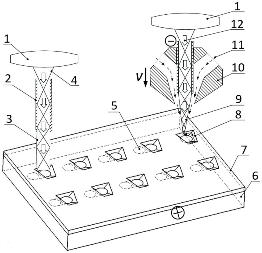
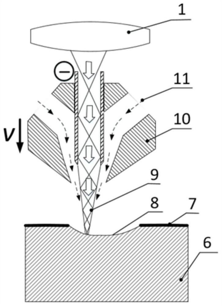
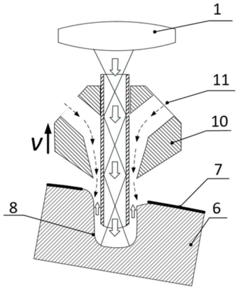
The invention discloses a method for achieving integrated machining of a special-shaped deep small hole with a thermal barrier coating by restraining liquid light transmission through dry ice, and relates to the field of combined machining in the non-traditional machining technology, and the method comprises a special-shaped hole machining stage and a deep small hole machining stage. Wherein the laser beam is totally reflected by the inner tube of the hollow tube electrode to obtain a plurality of laser beams, and the electrolyte flows through the hollow tube electrode; the metal substrate is connected with a positive electrode of the pulse power supply; a small deep hole is machined on the basis of machining of the special-shaped hole; in the special-shaped hole machining stage, laser machining is used as a main part, and water jet is used as an auxiliary part to remove materials; and in the deep small hole machining stage, materials are removed through the combined action of laser, electrolysis and water jet. According to the method, the diameter of a jet electrolyte water column is compressed through the dry ice fluid, the resolution ratio of the special-shaped hole machined through laser milling is remarkably improved, the machined surface is cooled, material layering is avoided, and integrated machining of the special-shaped hole and the small deep hole is achieved at the same station through one machining tool.

Description

technical field [0001] The invention relates to the field of composite processing in special processing technology, in particular to an integrated processing method for realizing special-shaped deep and small holes with a thermal barrier coating through dry ice-constrained liquid light transmission. Background technique [0002] Studies have shown that for every 50°C increase in the gas inlet temperature before the turbine, the engine efficiency can be increased by 10%. In order to obtain high efficiency and high thrust-to-weight ratio, the gas inlet temperature before the turbine is continuously increased. For example, the gas inlet temperature before the turbine of the American F119 engine reaches 2000K, which is higher than the melting point of most materials [1]. At present, to solve the high temperature problem, we mainly start from three aspects. First, the blade body is made of high-temperature-resistant high-temperature alloy material; second, a large number of air ...

Claims


Application Information

Patent Timeline
IPC IPC(8): B23H5/06B23H11/00B23K26/36B23K26/082B23K26/14B23K26/70
CPCB23H5/06B23H11/00B23K26/36B23K26/082B23K26/14B23K26/703Y02T50/60
Inventor 刘洋张朝阳鲁金忠薛伟朱浩徐坤曹宇张天帅吴明颐
Owner JIANGSU UNIV
Learn More