Micro-fluidic chip and preparation method thereof

A microfluidic chip and chip layer technology, applied in chemical instruments and methods, laboratory utensils, laboratory containers, etc., can solve the problems of complex processing and preparation, small deformation of micro valves, high price, etc., and achieve convenient High-magnification mirror imaging, improved deformation ability, and reduced processing difficulty

Active Publication Date: 2022-05-27
PEKING UNIV
View PDF7 Cites 0 Cited by
  • Summary
  • Abstract
  • Description
  • Claims
  • Application Information

AI Technical Summary

Problems solved by technology

In practice, the only viable option for imaging cells is a fluorescence microscope that does not require a light source, however, dyes, as well as UV lamps and filters, add cost, and the signal diminishes over time with exposure to light
And with the current side deflecting membrane microvalve, the design is not a real valve in nature because it does not completely seal the flow path, but a flow resistor
In addition, there are three types of sidewall effect channel cavities inside: top, bottom and side, which determine the deflection behavior of the deflection membrane, making this system more difficult to model compared to the three-layer membrane microvalve
[0006] In summary, various types of pneumatic microvalves in the prior art have several deficiencies, which are summarized as follows: 1. Multilayer pneumatic microvalves need to be aligned during processing, and the processing and preparation process is complicated; 2. Multilayer microvalve imaging Affected by the pneumatic layer, it is only suitable for fluorescent microscopes and is expensive; 3. The multi-layer microvalve has a thick bottom surface, which is not conducive to high-magnification imaging; 4. The current microvalve has small deformation and cannot completely close the liquid channel; 5. Current microvalves have different sidewall effects that are difficult to model

Method used


Image

  • Micro-fluidic chip and preparation method thereof
  • Micro-fluidic chip and preparation method thereof
  • Micro-fluidic chip and preparation method thereof

Examples


Embodiment Construction

[0033] The concept, specific structure and technical effects of the present invention will be clearly and completely described below with reference to the embodiments and the accompanying drawings, so as to fully understand the purpose, solutions and effects of the present invention. It should be noted that the embodiments in the present application and the features of the embodiments may be combined with each other in the case of no conflict.

[0034] It should be noted that, unless otherwise specified, when a feature is called "fixed" or "connected" to another feature, it can be directly fixed or connected to another feature, or it can be indirectly fixed or connected to another feature. on a feature. In addition, the descriptions of upper, lower, left, right, top, bottom, etc. used in the present invention are only relative to the mutual positional relationship of each component of the present invention in the accompanying drawings.

[0035] Also, unless otherwise defined,...


PUM


Abstract

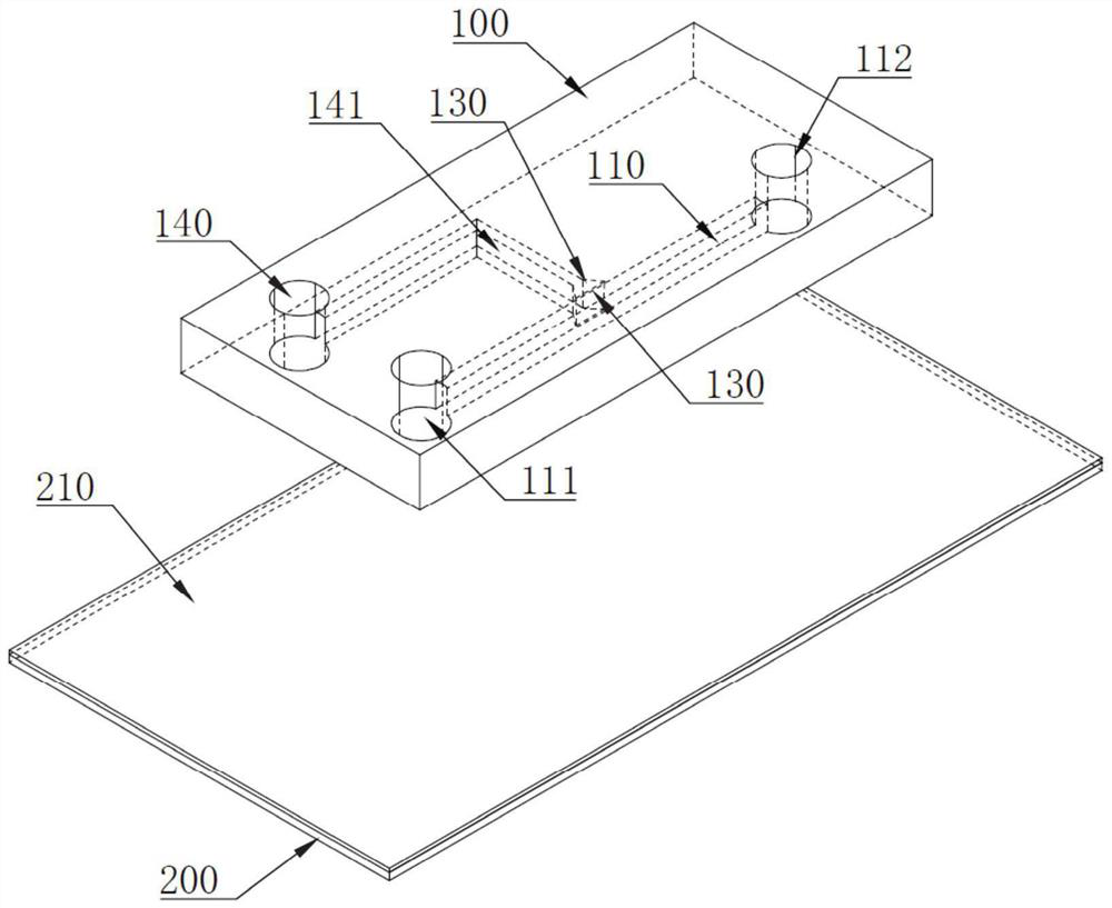
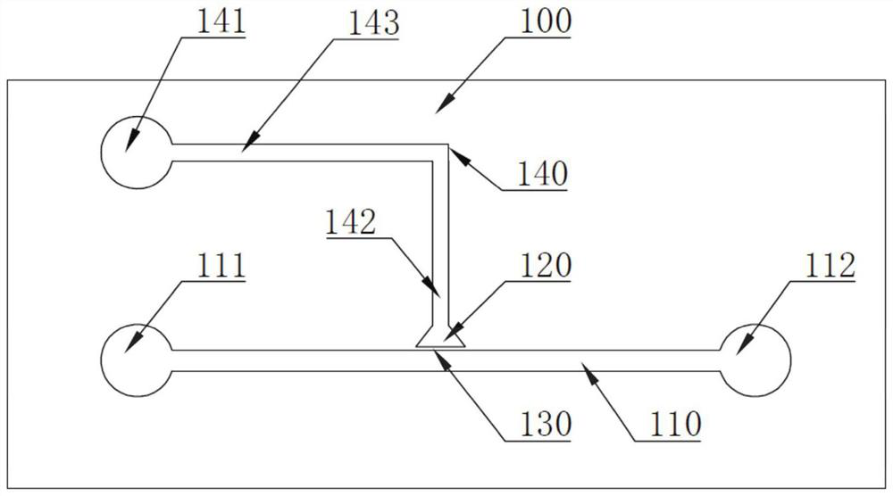
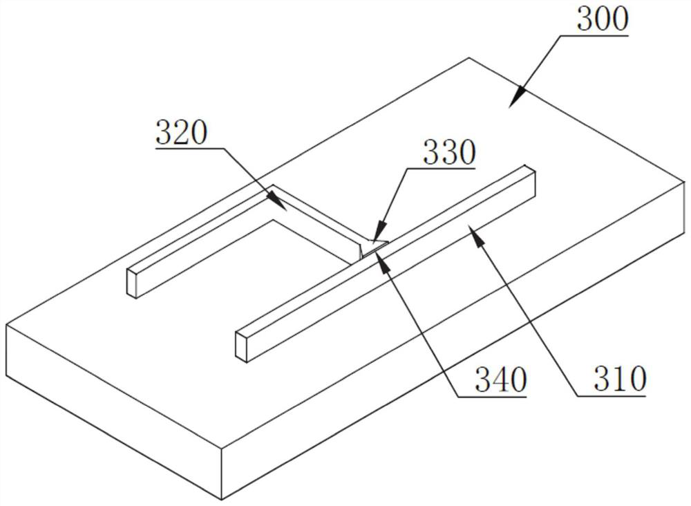
The invention relates to a micro-fluidic chip and a preparation method thereof, the micro-fluidic chip comprises a chip layer, a glass sheet, a liquid passing channel, a protruding part, an elastic wall and a pneumatic channel, the liquid passing channel, the protruding part, the elastic wall and the pneumatic channel are arranged on the same layer in the chip layer, the tail end of the pneumatic channel is communicated with the protruding part, and the elastic wall is arranged between the bottom end of the protruding part and one side edge of the pneumatic channel. The chip layer is further provided with an air pressure inlet, a liquid inlet and a liquid outlet, the air pressure inlet is communicated with the starting end of the pneumatic channel, and the liquid inlet and the liquid outlet are communicated with the two ends of the liquid passing channel respectively. According to the micro-fluidic chip and the preparation method thereof disclosed by the invention, compared with an existing pneumatic micro-valve with a multi-layer structure, a male mold corresponding to the multi-layer structure does not need to be manufactured, and alignment aiming at the multi-layer structure during bonding is also not needed, so that the processing technology is greatly simplified, and the processing difficulty of the micro-fluidic chip is greatly reduced.

Description

technical field [0001] The invention relates to a microfluidic chip and a preparation method thereof, belonging to the technical field of microfluidic chips. Background technique [0002] In microfluidic chips, pneumatic microvalves are driven by the pressure of soft materials to deform, which in turn blocks or releases fluid flow into the microsystem. [0003] During the development of the technical route of the microfluidic chip, some research groups proposed a "sandwich chip" to form a pneumatic microvalve in the microchannel. The chip consists of a pneumatic layer, a membrane wall and a liquid chip layer from top to bottom. Multilayer chip structure. The gas path and the liquid path of this chip are separated by a thin film wall and are vertically crossed in the top view direction, and the crossed part is the micro valve area. When pressure is applied to the pneumatic channels, the channels of the fluid layer can be selectively compressed and plugged, enabling fluid mo...

Claims


Application Information

Patent Timeline
Patent Type & Authority Applications(China)
IPC IPC(8): B01L3/00
CPCB01L3/5027B01L3/502707B01L2200/10B01L2300/0861B01L2300/0887B01L2300/12
Inventor 陈畅熊春阳瞿佳楠方旭林峰
Owner PEKING UNIV
Why Eureka
Try Eureka