Preparation method of ultrahigh-temperature anti-scouring thermal barrier coating

A thermal barrier coating, anti-scour technology, applied in the coating, superimposed layer plating, metal material coating process and other directions, can solve the problem that thermal barrier coating is difficult to have both ultra-high temperature resistance and anti-scour performance.

Pending Publication Date: 2022-05-27
EAST CHINA UNIV OF SCI & TECH +3
View PDF5 Cites 0 Cited by
  • Summary
  • Abstract
  • Description
  • Claims
  • Application Information

AI Technical Summary

Problems solved by technology

[0006] In order to solve the problem that the thermal barrier coating in the prior art is difficult to have both ultra-high temperature resistance and erosion resistance, the present invention provides a preparation method of an ultra-high temperature erosion-resistant thermal barrier coating

Method used


Image

  • Preparation method of ultrahigh-temperature anti-scouring thermal barrier coating
  • Preparation method of ultrahigh-temperature anti-scouring thermal barrier coating
  • Preparation method of ultrahigh-temperature anti-scouring thermal barrier coating

Examples


Embodiment 1

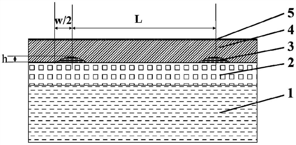
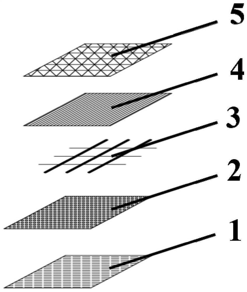
[0031] Step 1, for superalloy substrate 1 (see Figure 1-Figure 2 ) (that is, Hastelloy superalloy) for grinding, ultrasonic cleaning, and sandblasting pretreatment. The sandblasting process uses alumina with a particle size of 20-100 mesh to obtain a relatively uniform roughness.

[0032] In step 2, a metal bonding layer 2 is deposited on the superalloy substrate 1 by supersonic flame spraying (see Figure 1-Figure 2 ) (ie MCrAlY coating), wherein M is one or both of Ni and Co, and the thickness is about 200 μm.

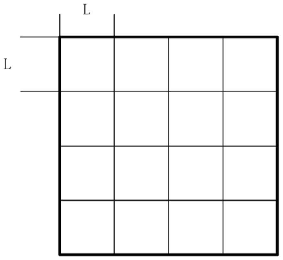
[0033] Step 3, using the laser engraving technology to introduce the grid bonding layer 3 with the same composition as the metal bonding layer 2 on the surface of the metal bonding layer 2 (see Figure 1-Figure 2 ) (ie MCrAlY mesh structure layer), the rated power of the fiber laser used is 1kW, the diameter of the laser beam spot is 0.9mm, the laser power is 120W, the scanning speed is 5mm / s, and the grid (ie, the grid bonding layer) The height h is 400 μm, and t...

Embodiment 2

[0038] Step 1, grinding, ultrasonic cleaning, and sandblasting pretreatment on the superalloy substrate 1 (ie, Ni-based single crystal superalloy).

[0039] In step 2, a metal bonding layer 2 (ie, a YHf micro-doped AlCrCoFeNi high-entropy bonding layer) is deposited on the superalloy substrate 1 by plasma spraying, with a thickness of about 200 μm, the atomic content of AlCrCoFeNi is 20%, and the doped YHf The atomic content is 0.2%.

[0040] Step 3, use laser engraving technology to introduce grid bonding layer 3 with the same composition as metal bonding layer 2 (ie, YHf micro-doped AlCrCoFeNi network structure layer) on the surface of metal bonding layer 2. The fiber laser used is rated for The power is 0.5 kW, the diameter of the laser beam spot is 0.3 mm, the laser power is 60 W, the scanning speed is 15 mm / s, the grid height h is 100 μm, and the grid width L is 900 μm.

[0041] In step 4, a layer of 8YSZ ceramic layer 4 with a thickness of about 500 μm is deposited on t...

Embodiment 3

[0045] Step 1, grinding, ultrasonic cleaning, and sandblasting pretreatment on the superalloy base 1 (ie, DZ125 superalloy).

[0046] Step 2, deposit a metal bonding layer 2 (ie, a YHf micro-doped AlCrCoFeNi high-entropy bonding layer) on the superalloy substrate 1 by plasma spraying, the thickness is about 100 μm, the Al atomic content is 10%, Cr, Co, Fe , Ni atomic content is 22.5%, and the doped YHf atomic content is 0.5%.

[0047] Step 3, use laser engraving technology to introduce grid bonding layer 3 with the same composition as metal bonding layer 2 (ie, YHf micro-doped AlCrCoFeNi network structure layer) on the surface of metal bonding layer 2. The fiber laser used is rated for The power is 0.8kW, the laser beam spot diameter is 0.6mm, the laser power is 90W, the scanning speed is 10mm / s, the grid height h is 150μm, and the grid width L is 600μm.

[0048] In step 4, a layer of 8YSZ ceramic layer 4 with a thickness of about 500 μm is deposited on the surface of the gri...


PUM

PropertyMeasurementUnit
thicknessaaaaaaaaaa
thicknessaaaaaaaaaa
thicknessaaaaaaaaaa

Abstract

The invention relates to a preparation method of an ultrahigh-temperature anti-scouring thermal barrier coating. The preparation method comprises the following steps: providing a high-temperature alloy matrix; depositing a metal bonding layer on the high-temperature alloy matrix; a grid bonding layer with the same components as the metal bonding layer is introduced to the metal bonding layer through the laser engraving technology or the laser coaxial powder feeding 3D printing technology, the grid bonding layer is composed of rectangular grid structures with regular shapes and protrudes out of the metal bonding layer, and the side length of each rectangular grid ranges from 100 micrometers to 900 micrometers; the height of the grid bonding layer is between 100 microns and 400 microns; and depositing a ceramic layer on the grid bonding layer. According to the preparation method of the ultrahigh-temperature anti-scouring thermal barrier coating, the continuous grid layer with the regular shape is introduced between the bonding layer and the ceramic layer, the roughness of an interface between the bonding layer and the ceramic layer is increased, the mechanical bonding strength of the interface is enhanced, and therefore the service temperature of the thermal barrier coating is increased.

Description

technical field [0001] The present invention relates to thermal barrier coatings, and more particularly to a preparation method of ultra-high temperature anti-scouring thermal barrier coatings. Background technique [0002] With the development of modern industry, higher service temperature requirements are put forward for hot-end components such as aero-engines. At higher service temperatures, both superalloy substrates and thermal protective coatings face higher performance requirements. Excessive temperature leads to oxidation and high temperature creep of the alloy surface matrix, which eventually leads to the failure of the superalloy. The thermal barrier coating can make full use of the superior low thermal conductivity of ceramic materials, and couple the ceramic with the high temperature substrate by coating to achieve the purpose of improving the service life and efficiency of the hot end components. [0003] At present, the main thermal barrier coating used is a d...

Claims


Application Information

Patent Timeline
Patent Type & Authority Applications(China)
IPC IPC(8): C23C4/073C22C30/00C23C4/129C23C4/134C23C24/10C23C4/11C23C4/18B23K26/362B23K26/60B23K26/70C23C28/00B22F10/25B22F10/38B33Y10/00
CPCC23C4/073C22C30/00C23C4/129C23C4/134C23C24/106C23C4/11C23C4/18B23K26/362B23K26/60B23K26/70C23C28/3215C23C28/3455B22F10/25B22F10/38B33Y10/00Y02T50/60
Inventor 张显程赵晓峰陈小龙龙东辉束国刚孙健刘伟王卫泽石俊秒涂善东王大力黄爱辉
Owner EAST CHINA UNIV OF SCI & TECH
Why Eureka
Try Eureka