Tail gas exhaust system, exhaust method and semiconductor equipment

A technology of exhaust and suction system and exhaust gas, which is used in semiconductor/solid-state device manufacturing, electrical components, program-controlled manipulators, etc., can solve problems such as low production efficiency, and achieve the effect of simple structure, good exhaust gas removal effect, and prevention of by-products.

Pending Publication Date: 2022-05-27
INST OF MICROELECTRONICS CHINESE ACAD OF SCI +1
View PDF0 Cites 0 Cited by
  • Summary
  • Abstract
  • Description
  • Claims
  • Application Information

AI Technical Summary

Problems solved by technology

[0006] In view of the above analysis, the present invention aims to provide an exhaust gas removal system, removal method and semiconductor equipment to

Method used


Image

  • Tail gas exhaust system, exhaust method and semiconductor equipment
  • Tail gas exhaust system, exhaust method and semiconductor equipment
  • Tail gas exhaust system, exhaust method and semiconductor equipment

Examples


Embodiment 1

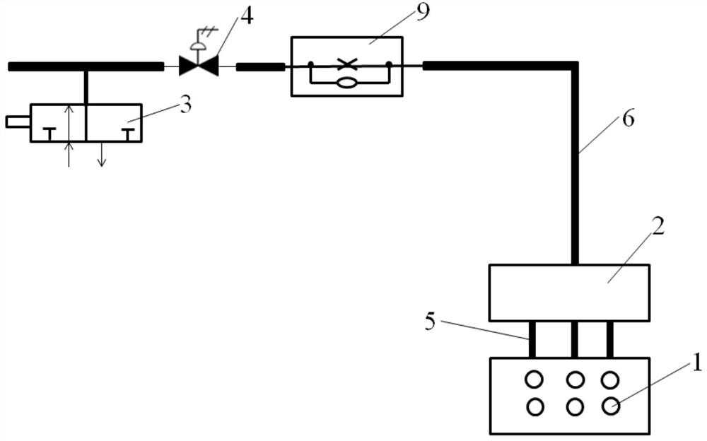
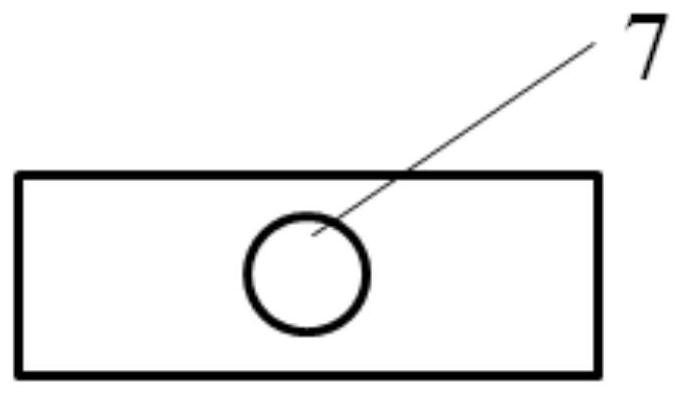
[0047] A specific embodiment of the present invention discloses a tail gas removal system, which is used to discharge the tail gas used in the process and remaining on the surface of the wafer. like figure 1 As shown in the figure, the exhaust gas removal system includes a plurality of micropores 1 arranged on the surface of the end effector arm and an exhaust gas suction system communicated with the micropores on the surface of the end effector arm. -Split), solenoid valve 3, pneumatic valve 4, discharge line and air extraction device (not shown in the figure).

[0048] It should be noted that, since the purpose of arranging the micro-holes is to remove the residual gas adsorbed on the surface of the wafer, the arrangement position of the micro-holes needs to be close to the wafer. Therefore, the preferred embodiment is to place the micro-holes on the surface of the end effector arm.

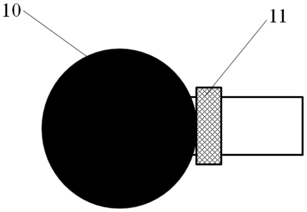
[0049] In a possible implementation manner, the region with micro-holes on the end effect...

Embodiment 2

[0062] Yet another embodiment of the present invention discloses a method for removing exhaust gas using the exhaust gas removal system of the first embodiment. The exhaust gas removal process will be described in detail below.

[0063] First, in the standby state of the equipment, turn on the exhaust gas removal system to exhaust for a certain period of time, the exhaust gas is sucked through a plurality of micropores on the surface of the end effector arm, mixed in the inner cavity of the multi-branch mixing chamber, and then passed through the second The exhaust line enters the atmosphere transfer module. The exhaust gas removal time depends on the situation, generally a few seconds to tens of minutes.

[0064] As for the timing of turning on the exhaust gas removal system, it can also be turned on when a wafer is placed on the end effector arm. Alternatively, turn on the exhaust gas removal system when the semiconductor manufacturing equipment is idle.

[0065] Next, th...

Embodiment 3

[0069] Another embodiment of the present invention discloses a semiconductor device including the exhaust gas removal system of the first embodiment.

[0070] Compared with the prior art, the present invention can achieve at least one of the following beneficial effects:

[0071] (1) The present invention does not solve the problem that the by-products are scattered on the wafer and cause defects in the wafer by replacing the end-effector arm after the by-product is generated, but through structural improvement (that is, setting micro-holes on the surface of the end-effector arm) ) Exhaust exhaust gas to prevent the generation of by-products, and fundamentally solve the problem of wafer defects caused by by-products scattered on the wafer.

[0072] (2) The tail gas removal system of the present invention has a simple structure and good effect of tail gas removal, and the product yield is improved after using the tail gas removal system.

[0073] (3) By controlling the diamete...


PUM

PropertyMeasurementUnit
Diameteraaaaaaaaaa
Spacingaaaaaaaaaa
Diameteraaaaaaaaaa

Abstract

The invention relates to a tail gas exhaust system, an exhaust method and semiconductor equipment, belongs to the technical field of semiconductor manufacturing, and solves the problem of low production efficiency caused by a mode of preventing byproducts from flying onto a wafer by replacing a tail end execution arm in the prior art. The tail gas exhaust system comprises a plurality of micropores formed in the surface of the tail end execution arm, a multi-branch mixing cavity, a control valve and an exhaust pipeline, the exhaust pipeline comprises a first exhaust pipeline located in the tail end execution arm and a second exhaust pipeline located outside the tail end execution arm, and a gas outlet and a plurality of gas inlets are formed in the multi-branch mixing cavity; the number of the air inlet holes is the same as that of the micropores, the micropores and the air inlet holes are connected through a first discharge pipeline, gas of the multiple micropores is collected in the multi-branch mixing cavity, and the air outlet holes and the control valve are connected through a second discharge pipeline. According to the invention, the generation of byproducts is fundamentally prevented.

Description

technical field [0001] The invention relates to the technical field of semiconductor manufacturing, and in particular, to an exhaust gas removal system, a removal method and semiconductor equipment. Background technique [0002] During semiconductor manufacturing, in the reaction chambers such as Cl 2 , HBr, BCl 3 In the process of picking up wafers from the pre-vacuum chamber (Airlock) by the end effector arm of the atmospheric transfer module robot after the process, and opening the wafer cassette ( When the FOUP is moving, the exhaust gas on the wafer surface is directly exposed to the atmosphere, and reacts with the moisture in the atmosphere to form by-products. When the robot of the atmospheric transmission module moves rapidly, the by-products randomly scatter, causing defects on the wafer and causing quality problems. At the same time, the by-products generated will contaminate the end effector, and the current semiconductor manufacturing equipment does not have an...

Claims


Application Information

Patent Timeline
IPC IPC(8): H01L21/67B25J9/12B25J9/16B25J19/00
CPCH01L21/67011B25J9/12B25J9/1679B25J19/00
Inventor 李相龙李俊杰李琳王佳周娜
Owner INST OF MICROELECTRONICS CHINESE ACAD OF SCI
Why Eureka
Try Eureka