Lead frame suitable for coplanar plastic package optocoupler packaging

A technology of lead frame and optocoupler, which is applied in the direction of semiconductor/solid-state device parts, semiconductor devices, electrical components, etc., can solve the problems of reliability impact, low curvature of photoconductive adhesive, and increase the types of raw materials in the plastic package of optocoupler, etc., to achieve The effect of reducing the probability of delamination, reducing the types of materials, and improving the connection strength

Pending Publication Date: 2022-05-27
XIAN MICROELECTRONICS TECH INST
View PDF0 Cites 0 Cited by
  • Summary
  • Abstract
  • Description
  • Claims
  • Application Information

AI Technical Summary

Problems solved by technology

The traditional lead frame has no design to control the diffusion of the photoconductive adhesive at the epitaxy of the substrate. The photoconductive adhesive is a viscous fluid, which will diffuse through the epitaxy of the substrate after dispensing, resulting in a too low arc of the photoconductive adhesive.
If the arc of the photoconductive adhesive is too low, it will affect the optical signal transmission between the light-emitting chip and the light-receiving chip, and the current transmission ratio of the product is not ideal. Therefore, the conventional method is to build a dam side wall near the extension to prevent the diffusion of the photoconductive adhesive before curing.
[0003] The cost of the dam material is high, and the introduction of it will also increase the types of raw materials in the optocoupler plastic package, increase the internal complexity of the product, and increase the risk of failure of the separation layer of the optocoupler plastic package when the working environment changes, which will affect product reliability. have a certain influence

Method used


Image

  • Lead frame suitable for coplanar plastic package optocoupler packaging
  • Lead frame suitable for coplanar plastic package optocoupler packaging
  • Lead frame suitable for coplanar plastic package optocoupler packaging

Examples


Embodiment 1

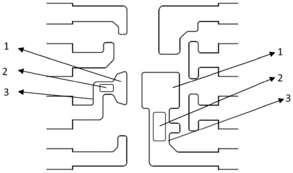
[0023] A lead frame suitable for coplanar plastic encapsulated optocoupler packages, such as figure 1 As shown in the figure, the lead frame substrate consists of two substrates 1, each part of the substrate 1 has the same function, both of which are used to carry the light-emitting chip or the light-receiving chip, the shape is approximately rectangular, and the area is different; one end of the substrate 1 passes through the lining The bottom epitaxial region 3 is connected with the inner pins, the flow suppression holes 2 are distributed on the substrate epitaxial region 3, and the flow suppression holes 2 are rounded rectangular flow suppression holes, which appear in the form of single holes. The length of the long side of the rounded rectangular flow suppression hole is 0.7 mm to 1.4 mm, and the distance from the edge of the flow suppression hole 2 to the edge of the substrate epitaxial region 3 is 0.2 mm to 0.5 mm. The single-rounded rectangular choke hole is suitable f...

Embodiment 2

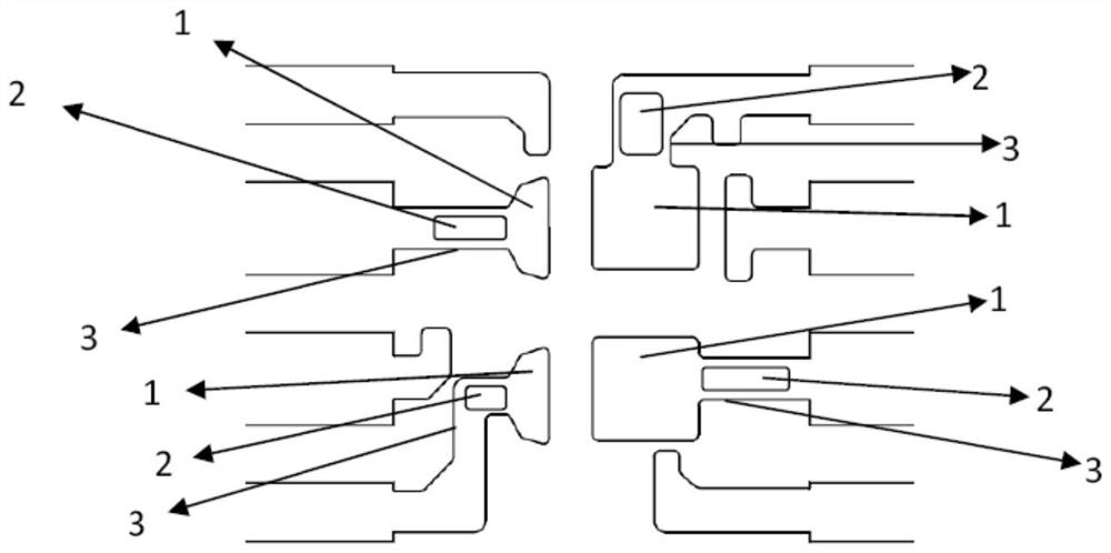
[0025] A lead frame suitable for coplanar plastic encapsulated optocoupler packages, such as figure 2 As shown, the lead frame substrate is composed of 4 substrates 1, the shape is approximately rectangular, the area is unequal, one end edge of each substrate 1 is connected to the inner pin, and the flow suppression holes 2 are distributed on the substrate epitaxy area 3, The flow suppression hole 2 is a rounded rectangular flow suppression hole in the form of a single hole. The size of the rounded rectangular flow suppression hole and the position on the epitaxial region 3 of the substrate are the same as those of the first embodiment.

Embodiment 3

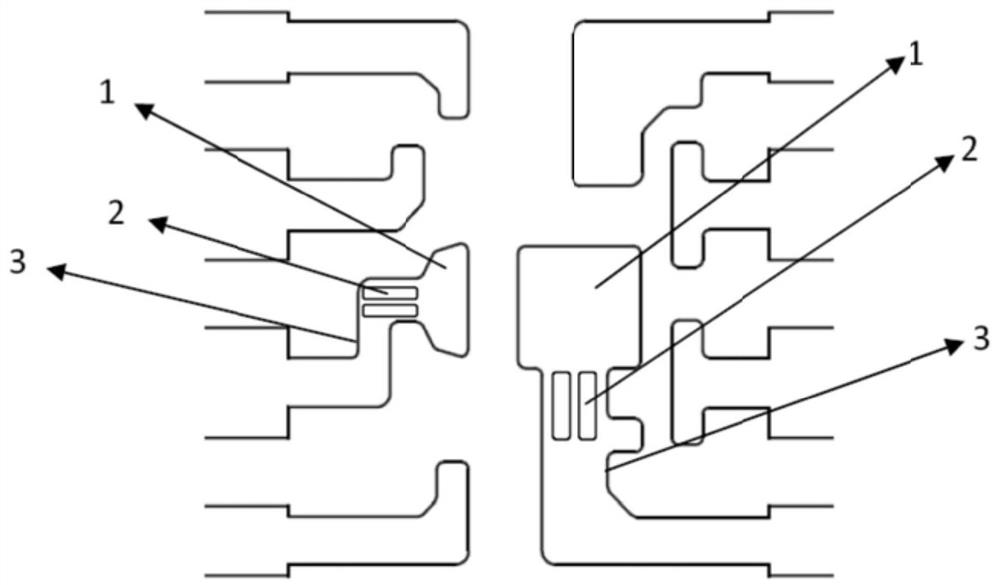
[0027] A lead frame suitable for coplanar plastic encapsulated optocoupler packages, such as image 3 As shown in the figure, the lead frame substrate is composed of two substrates 1, which are approximately rectangular in shape and different in area. The flow suppression hole 2 is a rounded rectangular flow suppression hole, which appears in the form of two rows and one column or one row and two columns.

[0028] The length of the long side of the rounded rectangular flow suppression holes arranged in two rows and a single row is 0.7 mm to 1.4 mm, and the distance from the outermost edge of the flow suppression hole 2 to the edge of the substrate epitaxial region 3 is 0.2 mm to 0.5 mm.

[0029] The length of the long side of the rounded rectangular flow suppression holes arranged in a single row and two columns is 0.3mm-0.7mm, and the distance from the outermost edge of the flow suppression hole 2 to the edge of the substrate epitaxial region 3 is 0.2mm-0.5mm. The multi-roun...


PUM

PropertyMeasurementUnit
lengthaaaaaaaaaa
lengthaaaaaaaaaa
pore sizeaaaaaaaaaa

Abstract

A substrate of the lead frame comprises a plurality of substrates, a flow suppression hole is formed in a substrate epitaxial region of each substrate, and the distance from the edge of the outermost side of the flow suppression hole to the edge of the substrate epitaxial region is 0.2 mm-0. 5 mm. The flow suppression holes are formed in the epitaxial area of the lead frame substrate, diffusion of the light guide glue is controlled through surface tension of the light guide glue under the condition that box dam glue is not used in the light guide glue dispensing process, the radian of the light guide glue is prevented from being reduced, the complexity of raw materials in a packaging body is reduced, the reliability of components is improved, box dam materials are omitted, and the production cost is reduced. And the cost is reduced.

Description

technical field [0001] The invention belongs to the field of optocoupler plastic packaging, in particular to a lead frame suitable for coplanar plastic packaging optocoupler packaging. Background technique [0002] The lead frame is one of the main basic materials for the plastic packaging production of integrated circuits. In the coplanar plastic-encapsulated optocoupler, it is necessary to wrap the light-emitting chip and the light-receiving chip on the lead frame substrate with photoconductive glue, so as to realize the connection between the light-emitting chip and the light-receiving chip. For signal transmission, the lead frame substrate is the dispensing area of ​​the photoconductive glue. The traditional lead frame has no design to control the diffusion of the photoconductive glue at the epitaxy of the substrate. The photoconductive glue is a viscous fluid. After dispensing, it will diffuse through the epitaxy of the substrate, resulting in an excessively low arc of ...

Claims


Application Information

Patent Timeline
Patent Type & Authority Applications(China)
IPC IPC(8): H01L23/495H01L23/31H01L25/16
CPCH01L23/49541H01L23/49537H01L23/3107H01L25/167H01L2224/48247H01L2224/48091H01L2224/8592H01L2924/00014
Inventor 张季春方兆国
Owner XIAN MICROELECTRONICS TECH INST
Why Eureka
Try Eureka