
Hydraulic motor pump with forced flow heat dissipation function

A technology of hydraulic motor and forced flow, which is applied to components of pumping devices for elastic fluids, machines/engines, liquid variable displacement machinery, etc., which can solve problems such as poor performance, and achieve performance improvement, temperature reduction, and reduction effect of influence

Pending Publication Date: 2022-05-31
HENAN UNIV OF SCI & TECH
View PDF11 Cites 0 Cited by
  • Summary
  • Abstract
  • Description
  • Claims
  • Application Information

AI Technical Summary

Problems solved by technology

[0006] The purpose of the present invention is to provide a hydraulic motor pump with the function of forced flow and heat dissipation, so as to solve the problem of poor performance of the hydraulic motor pump in the prior art due to the high internal temperature during use

Method used


Image

  • Hydraulic motor pump with forced flow heat dissipation function
  • Hydraulic motor pump with forced flow heat dissipation function
  • Hydraulic motor pump with forced flow heat dissipation function

Examples


specific Embodiment 1

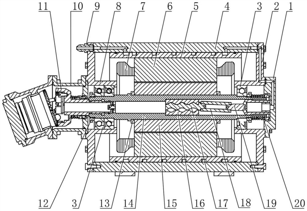
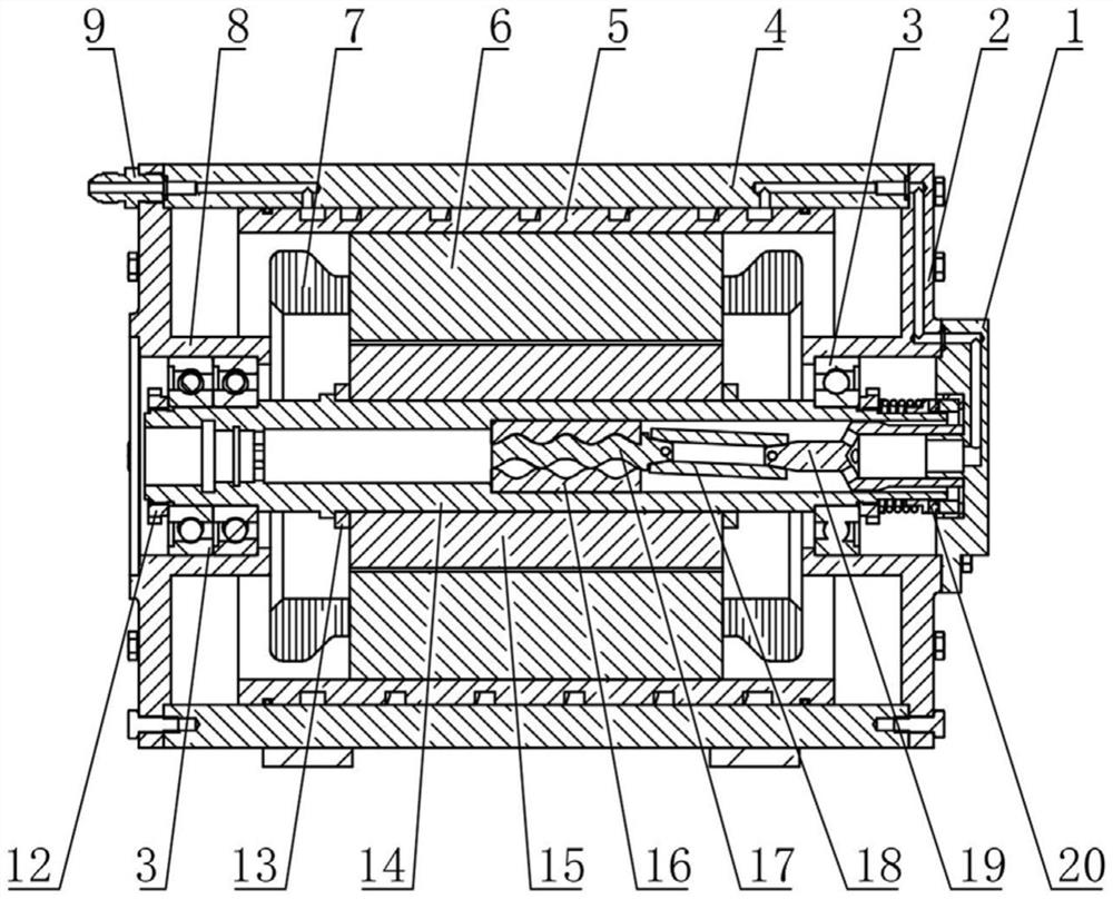
[0041] like figure 1 As shown, the hydraulic motor pump with forced flow heat dissipation function of the present invention includes a motor, a hydraulic pump and a transmission shaft 11, wherein the motor includes a motor casing, a stator 6, a rotor 15 and a rotating shaft 14, the stator 6 is provided with a coil 7, the rotor 15 is sleeved on the rotating shaft 14 and fixed by the rotor positioning ring 13, and the rotating shaft 14 is driven by the rotor 15 to rotate. In this embodiment, the hydraulic pump is an oblique axis pump, and the specific structure is the same as that of the oblique axis pump in the Chinese invention patent application with the application publication number CN114001007A. Since the specific structure of the oblique axis pump is not the protection point of the present invention, in the This will not be described in detail.

[0042] like figure 1 As shown, the left end of the motor casing is provided with a left end cover 8, and the right end is pro...

Embodiment 1

[0050] In Embodiment 1, the inner wall of the fixing sleeve is provided with a spiral groove, and a spiral rod serving as a central rod is inserted into the fixing sleeve. The outer peripheral surface of the spiral rod and the spiral groove together constitute a spiral pumping structure. In this embodiment, different from Embodiment 1, the inner wall of the fixing sleeve is provided with a spiral groove, the central rod is not inserted into the fixing sleeve, and the spiral pumping structure is formed only by the spiral groove.

specific Embodiment 3

[0052] The central rod in Example 1 is a screw rod. In this embodiment, the difference from Embodiment 1 is that the outer peripheral surface of the central rod is a rod with helical blades.


PUM


Abstract

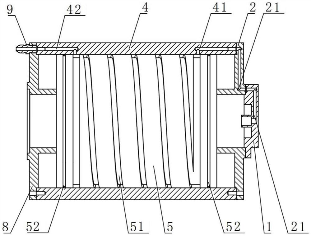
The invention belongs to the technical field of motor pumps, and particularly relates to a hydraulic motor pump with a forced flow heat dissipation function. A rotating shaft of a motor of the hydraulic motor pump with the forced flow heat dissipation function is provided with a rotating shaft cavity communicating with a transmission shaft cavity, a fixing sleeve with a cavity is fixed in the rotating shaft cavity, and a spiral pumping structure used for pumping fluid in the direction away from a transmission shaft is arranged in the fixing sleeve. The motor end cover is provided with an end cover cooling flow channel communicated with the rotating shaft cavity, the motor shell is provided with a motor shell cooling flow channel communicated with the end cover cooling flow channel, and the motor shell cooling flow channel is provided with a fluid outlet allowing fluid to flow out. In the working process, fluid in the rotating shaft cavity can cool the rotating shaft and the rotor and lower the temperature of the rotating shaft and the rotor, fluid in the motor shell cooling flow channel can cool the stator and lower the temperature of the stator, finally, the temperature of the whole motor is lowered, the influence of high temperature on the motor is reduced, and therefore the performance of the motor pump is improved.

Description

technical field [0001] The invention belongs to the technical field of motor pumps, and in particular relates to a hydraulic motor pump with a forced flow heat dissipation function. Background technique [0002] Hydraulic motor pump is to change the traditional series connection structure of motor, coupling and hydraulic pump into an integrated structure of motor and hydraulic pump. It has good dynamic characteristics, light weight, small structure size, simple installation and maintenance, and easy system integration, etc. Advantages, it has broad application prospects in aerospace, robotics and other mobile platforms. [0003] The Chinese invention patent application with the application publication number CN114001007A discloses an inclined axis plunger type hydraulic motor pump. The motor of the motor pump includes a rotor and a stator. The rotor is fixedly connected to the motor shaft, and the motor shaft is connected to the transmission shaft. The shaft is connected wi...

Claims


Application Information

Patent Timeline
Patent Type & Authority Applications(China)
IPC IPC(8): H02K5/20H02K9/19F04B1/2014F04B53/08F04B17/03
CPCH02K5/203H02K9/19F04B1/2014F04B53/08F04B17/03
Inventor 李东林刘明伟赵峰杨芳王帅王军华李阁强徐莉萍
Owner HENAN UNIV OF SCI & TECH
Learn More