Solar heat preservation device for vegetable cultivation
A heat preservation device and solar energy technology, which is applied in the field of heat preservation devices for vegetable cultivation, can solve the problems of poor heat preservation performance of plastic film, unsatisfactory heat preservation effect, and affect the growth speed of vegetables, etc., and achieve the effects of reducing consumption, good heat preservation, and preventing drying and withering
- Summary
- Abstract
- Description
- Claims
- Application Information
AI Technical Summary
Problems solved by technology
Method used
Image
Examples
Embodiment 1
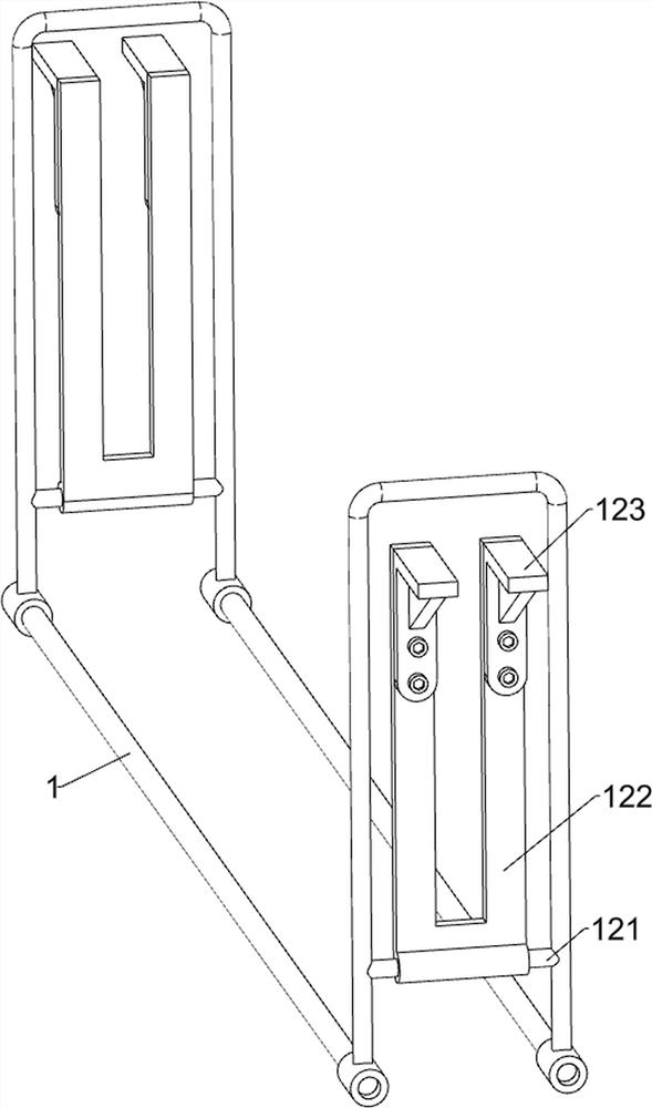
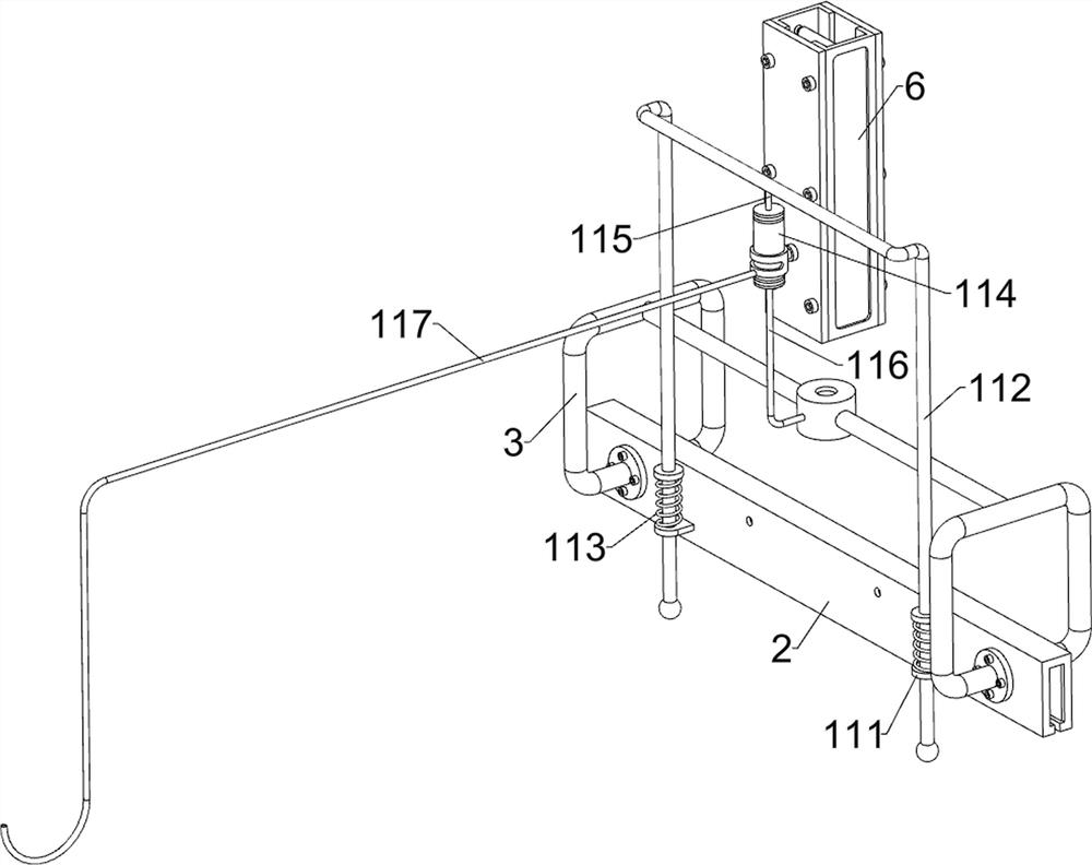
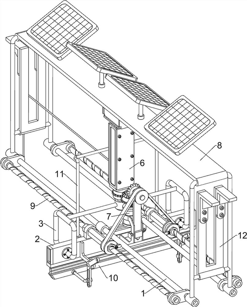
[0031] combine Figure 1-2 As shown, the application provides a solar heat preservation device for vegetable cultivation, which includes a guide frame 1, a frame body 2, an air intake pipe 3, a cylinder 4, a ring gear 5, a heater 6, an extraction assembly 7 and a power generation assembly 8, and the guide The frame body 2 is slidingly connected to the lower part of the frame 1, and the frame body 2 is used to spray hot air to keep the cultivated vegetables warm. The frame body 2 is connected to the air intake pipe 3 by means of bolt connection, and the middle and upper part of the air intake pipe 3 is connected to a cylinder. 4. The middle part of the cylinder 4 is slidingly connected to the ring gear 5 through a circular chute, and the top of the cylinder 4 is connected to the heater 6. The heater 6 is used to heat the air. The extraction assembly 7 is used to draw air into the cylinder 4, and the guide frame 1 is provided with a power generation assembly 8, which is used to ...
Embodiment 2
[0036] On the basis of Example 1, combined with figure 1 and Figure 5 As shown, a moving assembly 9 is also included. A moving assembly 9 is arranged between the support 72, the guide frame 1 and the reduction motor 73. The moving assembly 9 is used to drive the frame body 2 to reciprocate and spray hot air evenly on the cultivated vegetables for heat preservation. , the moving assembly 9 includes a fixed plate 91, a rotating shaft 92, a bevel gear 93, a reciprocating screw rod 94, a first positioning block 95, a nut 96, a pulley 97 and a flat belt 98, and the right side of the bracket 72 is connected with a fixed Plate 91, fixed plate 91 tops are connected with rotating shaft 92 by bearing, are connected with bevel gear 93 on the left side of rotating shaft 92 and the output shaft of deceleration motor 73, two bevel gears 93 meshing, are connected with reciprocating wire symmetrically before and after on the guide frame 1. Rod 94, two reciprocating screw rods 94 are all con...
Embodiment 3
[0039] On the basis of Example 2, combined with figure 1 and Image 6 As shown, a swing assembly 10 is also included. A swing assembly 10 is provided between the pulley 97 and the frame body 2. The swing assembly 10 is used to increase the spraying area of hot gas. The swing assembly 10 includes a contact block 101, a support plate 102, a swing The plate 103, the first cross bar 104, the air outlet frame 105 and the tie rod 106 are connected with the contact block 101 at the eccentric position on the right side of the two pulleys 97 on the lower side, and the front and rear sides of the frame body 2 are connected symmetrically by welding. There are support plates 102, and the two support plates 102 are rotatably connected with a swing plate 103, and a first cross bar 104 is connected between the tops of the two swing plates 103, and the contact block 101 can rotate to contact with the first cross bar 104, and the frame The air outlet frame 105 is connected to the bottom of ...
PUM
 Abstract
Description
Claims
Application Information
 - R&D
- Intellectual Property
- Life Sciences
- Materials
- Tech Scout
- Unparalleled Data Quality
- Higher Quality Content
- 60% Fewer Hallucinations
Browse by: Latest US Patents, China's latest patents, Technical Efficacy Thesaurus, Application Domain, Technology Topic, Popular Technical Reports.
© 2025 PatSnap. All rights reserved.Legal|Privacy policy|Modern Slavery Act Transparency Statement|Sitemap|About US| Contact US: help@patsnap.com


