
SOI LIGBT device with planar combined auxiliary electrode structure and preparation method of SOI LIGBT device

A technology for auxiliary electrodes and auxiliary electrode layers, which is applied in semiconductor/solid-state device manufacturing, electrical components, semiconductor devices, etc., can solve the problems of difficult breakdown voltage and low forward conduction voltage drop, and achieve the optimization of lateral electric field and longitudinal Effect of electric field distribution, reduction of forward voltage drop, and increase of device power consumption

Pending Publication Date: 2022-06-07
XIDIAN UNIV
View PDF0 Cites 0 Cited by
  • Summary
  • Abstract
  • Description
  • Claims
  • Application Information

AI Technical Summary

Problems solved by technology

[0004] The purpose of the present invention is to solve the technical problem that SOI LIGBT devices are difficult to balance high breakdown voltage, low forward conduction voltage drop, and specific on-resistance, and propose a SOI LIGBT device with a planar combined auxiliary electrode structure and its preparation method to further optimize the contradictory relationship between the breakdown voltage of SOI LIGBT devices and the forward conduction voltage drop and specific on-resistance to improve the performance of SOI LIGBT devices

Method used


Image

  • SOI LIGBT device with planar combined auxiliary electrode structure and preparation method of SOI LIGBT device
  • SOI LIGBT device with planar combined auxiliary electrode structure and preparation method of SOI LIGBT device
  • SOI LIGBT device with planar combined auxiliary electrode structure and preparation method of SOI LIGBT device

Examples


Embodiment Construction

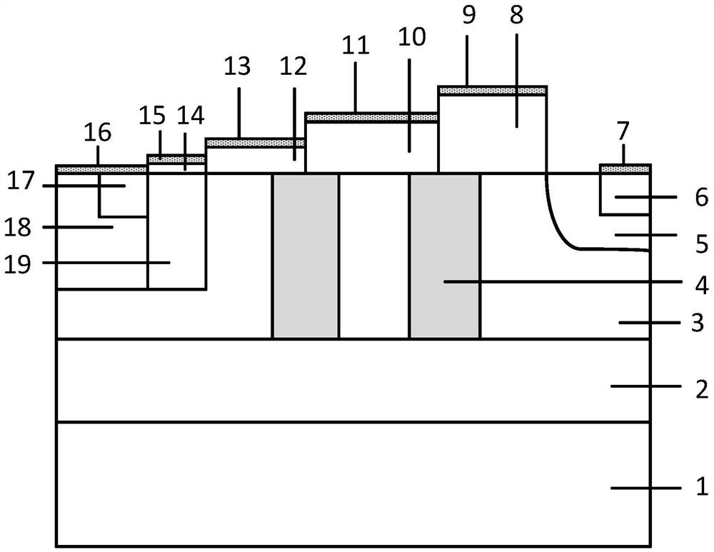
[0052] In the present embodiment, "up", "down" is along the P-type semiconductor material substrate 1 to N type drift zone 3 direction for bottom to top, "thickness" is measured in the direction perpendicular to the N type drift zone 3, "width" is measured in the direction of the gate oxide layer 14 to N type buffer layer 5.

[0053] See Figure 1 , the present embodiment provides a SOI LIGBT device having a planar combination auxiliary electrode structure, the SOILIGBT device comprising a sequentially cascaded P-type semiconductor material substrate 1, SOI base 2 and N-type drift region 3, wherein the thickness of the P-type semiconductor material substrate 1 is 5 to 20μm; The doping concentration of P-type semiconductor material substrate 1 is 5×10 13 cm -3 ~5×10 14 cm -3 ; The thickness of SOI base 2 is 2~4μm; The thickness of N-type drift zone 3 is 2~5μm; The doping concentration of N-type drift zone 3 is 1.0×10 14 ~1.0×10 16 cm -3 。

[0054] N-type drift zone 3 from one side t...


PUM

PropertyMeasurementUnit
thicknessaaaaaaaaaa
thicknessaaaaaaaaaa
thicknessaaaaaaaaaa

Abstract

The invention relates to an SOI (Silicon On Insulator) LIGBT (Lateral Insulated Gate Bipolar Transistor) device with a planar combined auxiliary electrode structure and a preparation method of the SOI LIGBT device, aiming at solving the technical problem that the SOI LIGBT device is difficult to consider relatively high breakdown voltage and relatively low forward conduction voltage drop and specific conduction resistance at the same time. The device comprises a P-type semiconductor material substrate, an SOI base and an N-type drift region which are sequentially stacked, and an emitter region, a P-type base region and an N-type buffer layer are sequentially formed from one side to the other side of the N-type drift region; a plurality of gradually increased auxiliary electrode structures are sequentially formed between the P-type base region and the N-type buffer layer; a P column is arranged below two adjacent auxiliary oxide layers; the auxiliary electrode structure and a part of the P column abutting against the auxiliary electrode structure form a planar combined auxiliary electrode. The method comprises the following steps: doping above an SOI (Silicon On Insulator) base to form an N-type drift region and a P-type base region; forming a P column and an N-type buffer layer in the N-type drift region; and an auxiliary electrode structure is formed between the P-type base region and the N-type buffer layer.

Description

Technical field [0001] The present invention relates to a semiconductor power device, specifically to a SOILIGBT device having a planar combinatorial auxiliary electrode structure and a preparation method thereof. Background [0002] Transversely insulated gate bipolar metal oxide semiconductor field effect transistor (Insulated Gate BipolarTransistor, referred to as IGBT) can take into account the voltage drive, safe operating area width and high switching speed characteristics of longitudinal double diffusion field effect transistors, while taking into account the low on-resistance and high current density characteristics of power bipolar transistors, so it has received widespread attention at home and abroad. [0003] SOI LIGBTs are favored by researchers for their higher load capacity and ease of integration. When SOI LIGBT is in a blocked state, its withstand voltage mainly depends on the base region, drift region, buffer layer doping concentration and size and other paramet...

Claims


Application Information

Patent Timeline
Patent Type & Authority Applications(China)
IPC IPC(8): H01L29/739H01L29/40H01L21/331
CPCH01L29/7394H01L29/404H01L29/66325
Inventor 段宝兴唐春萍王彦东杨银堂
Owner XIDIAN UNIV
Learn More