Polishing device and method based on engineering machinery

A technology for construction machinery and grinding mechanisms, applied in grinding/polishing safety devices, grinding machines, manufacturing tools, etc., can solve problems such as hidden dangers, wastes that easily hurt operators, and troublesome operations, and achieve the effect of avoiding safety accidents.

Active Publication Date: 2022-06-21
徐州阳森建设科技有限公司
View PDF8 Cites 1 Cited by
  • Summary
  • Abstract
  • Description
  • Claims
  • Application Information

AI Technical Summary

Problems solved by technology

[0004] During grinding, with the high-speed rotation of the grinding machine, a large amount of waste will be splashed and scattered in the production workshop. Among them, during the grinding process, the operator needs to adjust the position of the grinding, and the grinding part will be ground Smooth, however, not only makes the operation more troublesome, but also the splashed waste is easy to accidentally injure the operator, posing a certain safety hazard

Method used


Image

  • Polishing device and method based on engineering machinery
  • Polishing device and method based on engineering machinery
  • Polishing device and method based on engineering machinery

Examples


Embodiment 1

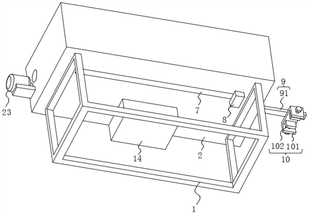
[0041] A grinding device based on construction machinery, comprising:
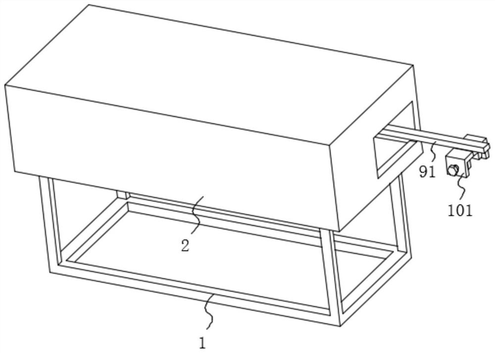
[0042] rack 1;

[0043] a box body 2, the box body 2 is fixed on the frame 1;

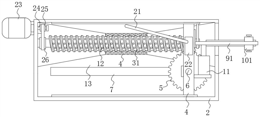
[0044] Grinding mechanism 3, the grinding mechanism 3 is arranged inside the box body 2, and the grinding mechanism 3 includes a grinding tooth sleeve 31, and the grinding tooth sleeve 31 is rotatably connected to one side of the inside of the box body 2, and used for rough machining the grinding piece, the grinding tooth sleeve 31 is provided with a grinding pad 32 inside, and is used for finishing the grinding piece;

[0045] A displacement plate 4, the displacement plate 4 is slidably connected to both sides of the inside of the box body 2, and a gear 5 is rotatably connected to the displacement plate 4, and a rotating shaft 6 is rotatably connected to the gear 5;

[0046] A through slot 7, the through slot 7 is opened at the bottom of the box body 2, and the interior of the through slot 7 is slidably connected with a slid...

Embodiment 2

[0081] see Image 6 - Figure 8 :

[0082] A fixing plate 27 is fixedly connected to the displacement plate 4 , one side of the fixing plate 27 penetrates the box body 2 and extends to one side of the box body 2 , and the fixing plate 27 extends to the box body The outside of 2 is fixedly connected with a sleeve 28 through a connecting rod, and the inside of the sleeve 28 is provided with a brush cylinder 29 for cleaning the waste debris left by the grinding of the inner wall of the grinding tooth sleeve 31;

[0083] The provided brush cylinder 29 can enter the interior of the grinding tooth sleeve 31, and by contacting the inner wall of the grinding tooth sleeve 31, the remaining waste chips are swept and released from the circular hole 12, And release from the right opening of the grinding tooth sleeve 31 (at this time, the grinding piece has been separated from the grinding tooth sleeve 31, and will not affect the cleaning of the inner wall of the grinding tooth sleeve 31...


PUM


Abstract

The invention discloses a polishing device and method based on engineering machinery, and relates to the technical field of engineering machinery. The box body is fixed on the machine frame; the grinding mechanism is arranged in the box body, the grinding mechanism comprises a grinding tooth sleeve, and the grinding tooth sleeve is rotationally connected to one side of the interior of the box body and used for conducting rough machining on a grinding part. According to the grinding device, the clamping mechanism is arranged on the grinding tooth sleeve, the grinding piece on the clamping mechanism is pushed to automatically enter the grinding tooth sleeve, the grinding piece is ground during rotation of the grinding tooth sleeve, the grinding tooth sleeve is discharged during rotation through the formed round hole and then falls into the discharging bin to be collected, in the process, automatic feeding and discharging of the grinding piece are achieved, manual operation is not needed, and the working efficiency is improved. Time and labor are saved, and safety accidents are avoided.

Description

technical field [0001] The invention relates to the technical field of construction machinery, and more particularly, to a grinding device and method based on construction machinery. Background technique [0002] Construction machinery is an important part of the equipment industry. In a nutshell, the machinery and equipment necessary for comprehensive mechanized construction projects required for earthwork construction projects, road construction and maintenance, mobile lifting and unloading operations and various construction projects. It is construction machinery, among which construction machinery is mainly used in national defense construction projects, transportation construction, energy industry construction and production, mining and other raw material industrial construction and production, agriculture, forestry and water conservancy construction, industrial and civil construction, urban construction, environmental protection and other fields. [0003] Construction ...

Claims


Application Information

Patent Timeline
Patent Type & Authority Applications(China)
IPC IPC(8): B24B27/00B24B41/02B24B55/12B24B41/06B24B41/00
CPCB24B27/00B24B41/02B24B55/12B24B41/06B24B41/005
Inventor 周娟池沛李志坚王留红
Owner 徐州阳森建设科技有限公司
Why Eureka
Try Eureka