
Two-dimensional pupil-expanding binocular waveguide near-to-eye display device and augmented reality display equipment

A near-eye display and binocular technology, applied in the direction of optical waveguide light guide, instrument, optics, etc., can solve the problems of affecting user experience and increasing the volume of the device, and achieve the effect of reducing volume and weight, simple structure and low process requirements

Pending Publication Date: 2022-06-21
北京谷东网科技有限公司
View PDF3 Cites 7 Cited by
  • Summary
  • Abstract
  • Description
  • Claims
  • Application Information

AI Technical Summary

Problems solved by technology

[0003] In the AR near-eye display system, the core optical hardware part is the waveguide coupling element, and most of the waveguide coupling elements can only realize the expansion of the exit pupil of the light in the waveguide transmission direction, and the exit pupil perpendicular to the waveguide transmission direction will be With the transmission of light in the waveguide, it gradually decreases. In order to ensure the exit pupil diameter at the wearing position of the human eye, the exit pupil of the optical-mechanical collimation system in front of the waveguide element needs to be large enough perpendicular to the transmission direction of the waveguide. At the same time, if you want Obtaining a larger field of view will lead to an increase in the size of the device, which will affect the user experience

Method used


Image

  • Two-dimensional pupil-expanding binocular waveguide near-to-eye display device and augmented reality display equipment
  • Two-dimensional pupil-expanding binocular waveguide near-to-eye display device and augmented reality display equipment

Examples


Embodiment Construction

[0031] Exemplary embodiments will be described in detail herein, examples of which are illustrated in the accompanying drawings. Where the following description refers to the drawings, the same numerals in different drawings refer to the same or similar elements unless otherwise indicated. The implementations described in the illustrative examples below are not intended to represent all implementations consistent with this disclosure. Rather, they are merely examples of apparatus and methods consistent with some aspects of the present disclosure as recited in the appended claims.

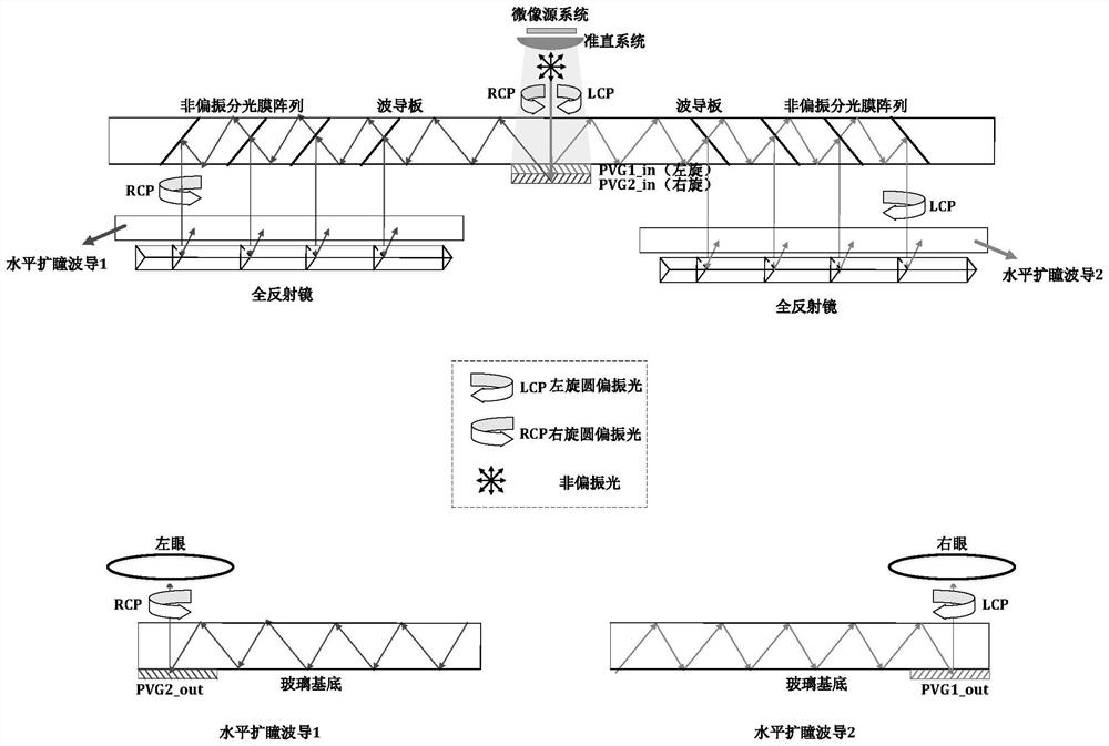
[0032] figure 1 It is a schematic structural diagram of a two-dimensional pupil-dilated binocular waveguide near-eye display device according to an exemplary embodiment.

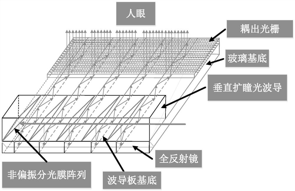
[0033] like figure 1 shown and figure 2 As shown, a two-dimensional pupil-expanded binocular waveguide near-eye display device includes: an opto-mechanical system, a coupled-in diffractive optical element group, a vertical pu...


PUM

PropertyMeasurementUnit
thicknessaaaaaaaaaa

Abstract

The invention relates to a two-dimensional pupil-expanding binocular waveguide near-eye display device and augmented reality display equipment, the two-dimensional pupil-expanding binocular waveguide near-eye display device comprises an optical-mechanical system for loading and outputting an image and emitting the collimated and corrected image to a coupling-in diffraction optical element group; the coupling-in diffraction optical element is formed by stacking and compounding a first polarization body holographic grating and a second polarization body holographic grating so as to be coupled into the left-hand circularly polarized light beam and the right-hand circularly polarized light beam respectively; the vertical pupil expanding optical waveguide is used for carrying out light ray expansion on the left-handed circularly polarized light beam and the right-handed circularly polarized light beam in the vertical direction so as to couple out multiple light rays to the glass substrate; the total reflection mirror deflects the light emitted by the vertical pupil-expanding optical waveguide at a preset angle and then emits the light into the glass substrate at a target angle capable of meeting a total reflection condition; the glass substrate is used for transmitting the light emitted by the vertical pupil-expanding optical waveguide to the coupling-out grating in a total reflection manner; and the coupling-out grating is used for coupling out the light rays to the left eye and the right eye of a person respectively.

Description

technical field [0001] The present disclosure relates to the technical field of augmented reality display, and in particular, to a two-dimensional pupil dilated binocular waveguide near-eye display device and an augmented reality display device. Background technique [0002] Augmented reality (AR) technology has been widely used in military, industrial design and manufacturing, medical, entertainment and education fields due to its unique feature of superimposing projected images to the real environment perceived by users. Even changing some information interaction methods in production and life in all walks of life has huge potential application value. [0003] In the AR near-eye display system, the core optical hardware part is the waveguide coupling element, and most of the waveguide coupling elements can only realize the exit pupil expansion of the light in the transmission direction of the waveguide, and the exit pupil perpendicular to the transmission direction of the ...

Claims


Application Information

Patent Timeline
Patent Type & Authority Applications(China)
IPC IPC(8): G02B27/00G02B27/01G02B6/10G02B5/18
CPCG02B27/0081G02B27/0103G02B6/10G02B5/1814G02B5/1819
Inventor 李艳崔海涛李星
Owner 北京谷东网科技有限公司
Learn More