Multi-core optical fiber, transmission system and multi-core optical fiber capacity expansion method
A technology of multi-core optical fiber and transmission system, which is applied in the field of transmission system and multi-core optical fiber expansion, multi-core optical fiber, and can solve the problems that cannot support the application of ultra-long-distance weakly coupled multi-core transmission system
- Summary
- Abstract
- Description
- Claims
- Application Information
AI Technical Summary
Problems solved by technology
Method used
Image

Examples
Embodiment 1
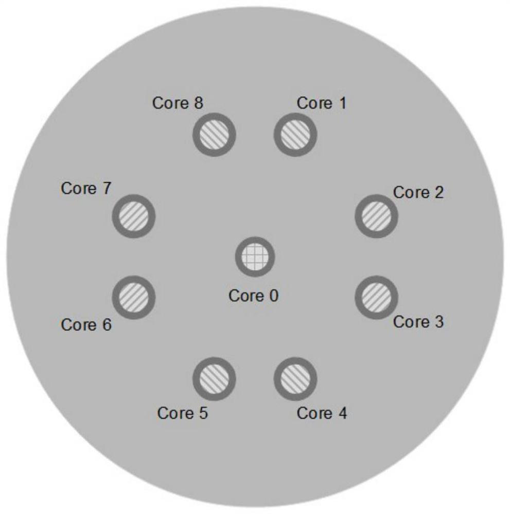
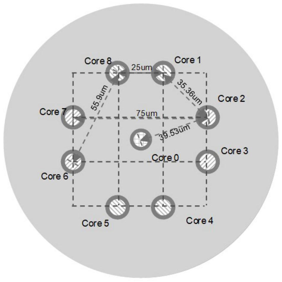
[0038] figure 1 A schematic cross-sectional view of a multi-core optical fiber provided in an embodiment of the present application. like figure 1 As shown, the multi-core optical fiber provided by the present application includes 9 cores (Core0-Core8). Among them, the core (Core 0) located at the center of the multi-core fiber is called the central core, and the eight cores (Core1-Core8) located around the core (Core 0) are called the surrounding cores.
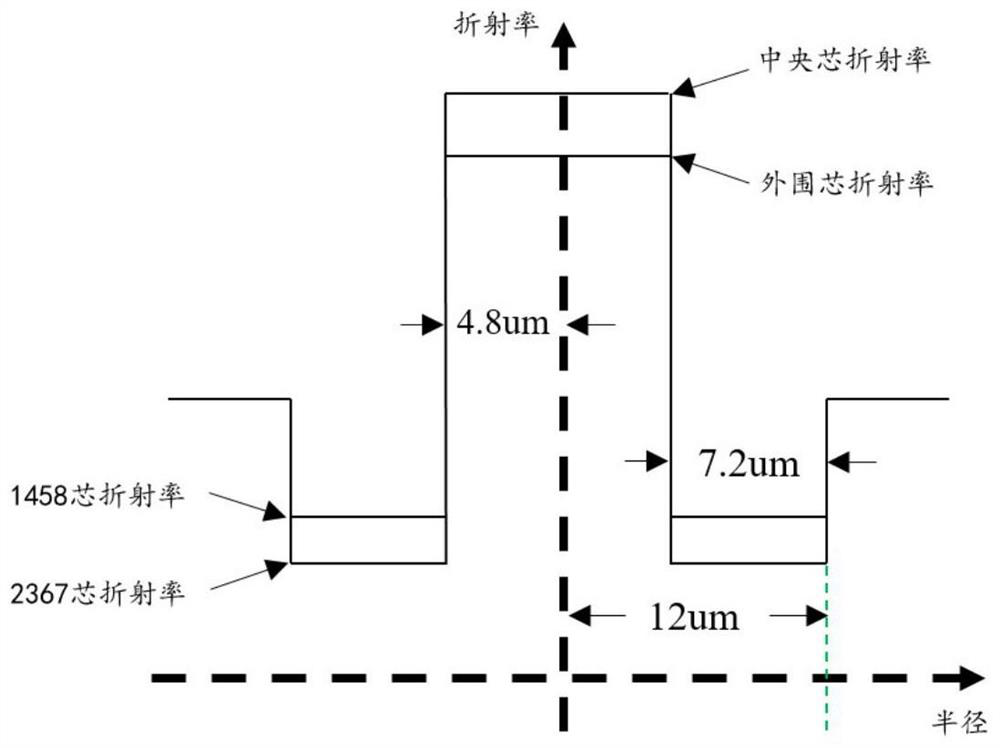
[0039] For the central core (Core0), in order to have no coupling with other surrounding cores (Core0-Core8), a channel layer with a low refractive index is provided to suppress crosstalk with the surrounding cores (Core0-Core8). question. In addition, the central core (Core0) is doped with germanium to make its optical performance compatible with the optical parameters of the existing standard single-mode fiber (ITU-T G.652 standard), so that the central core (Core0) can be compatible with other Optical fibers with a ce...
Embodiment 2
[0061] Figure 5 This is a schematic structural diagram of a multi-core optical fiber transmission system provided in an embodiment of the present application. like Figure 5 As shown, the system includes N optical terminal multiplexers (OTM) 501, M optical line amplifiers (OLA) 502 and L optical fibers 503, and N and M are positive values greater than 2 Integer, L is a positive integer greater than 3. Wherein, each OTM 501 is connected to an OLA 502 through an optical fiber, one end of each OLA 502 is connected to the OTM 501 , and the other end is connected to one end of another OLA 502 .
[0062] The OTM 501 includes an optical transponder unit (OTU) 5011 , a wavelength multiplexer / demultiplexer (W Mux / W DMux) 5012 and a fan-in / fan-out device 5013 .
[0063] OTU 5011 can be divided into existing single wavelength or frequency super channel OTU and space super channel OTU. Among them, the existing single-wavelength or frequency super-channel OTU is connected to one fib...
Embodiment 3
[0070] 6(a)-(d) are diagrams of the evolution process from single-mode optical fiber smoothing to multi-core optical fiber provided by the embodiments of the present application.
[0071]As shown in FIG. 6( a ), an existing single-mode optical fiber transmission system includes two OTMs, two OLAs (including two single-mode optical fiber amplifiers) and single-mode optical fibers. Among them, one OTM is deployed at the near end (take the left OTM as an example, the same below), and the other OTM is deployed at the far end (take the right OTM as an example, the same below). The demultiplexer is connected to an OLA through a single-mode fiber to compensate for fiber attenuation, and then the OLAs at both ends are connected to the single-mode fiber between the near-end and the far-end respectively, thereby constructing a single-mode fiber transmission system.
[0072] In the signal transmission process, after the optical signal is sent by the near-end OTM, it is transmitted to the...
PUM
| Property | Measurement | Unit |
|---|---|---|
| radius | aaaaa | aaaaa |
| radius | aaaaa | aaaaa |
| width | aaaaa | aaaaa |
Abstract
Description
Claims
Application Information
 - R&D
- Intellectual Property
- Life Sciences
- Materials
- Tech Scout
- Unparalleled Data Quality
- Higher Quality Content
- 60% Fewer Hallucinations
Browse by: Latest US Patents, China's latest patents, Technical Efficacy Thesaurus, Application Domain, Technology Topic, Popular Technical Reports.
© 2025 PatSnap. All rights reserved.Legal|Privacy policy|Modern Slavery Act Transparency Statement|Sitemap|About US| Contact US: help@patsnap.com