Directional powder feeding device and selective laser melting forming equipment

A technology of laser selective melting and powder feeding device, which is applied in the field of additive manufacturing and can solve the problems of inability to evenly arrange the metal matrix powder and the diamond in the alignment and orientation.

Active Publication Date: 2022-06-24
CHINA UNIV OF GEOSCIENCES (WUHAN)
View PDF5 Cites 0 Cited by
  • Summary
  • Abstract
  • Description
  • Claims
  • Application Information

AI Technical Summary

Problems solved by technology

[0006] In view of this, the embodiment of the present invention provides a directional powder feeding device and laser selective melting molding equipment, aiming to solve the problem that the traditional powder spreading system of the existing laser selective melting molding equipment cannot orient the metal matrix powder and diamond arrangement evenly aligned problem

Method used


Image

  • Directional powder feeding device and selective laser melting forming equipment
  • Directional powder feeding device and selective laser melting forming equipment
  • Directional powder feeding device and selective laser melting forming equipment

Examples


Embodiment 1

[0065] Example 1, the diamond particle size is 38um, the particle shape is a complete regular octahedron, the matrix metal powder is a commercial CoCrMo alloy, the sphericity of the alloy powder is greater than 99%, and the particle size of the powder used is 38um. The volume proportion of diamond particles is 20%. The workable area of ​​the substrate 13 is selected as a square of 8cm*8cm.

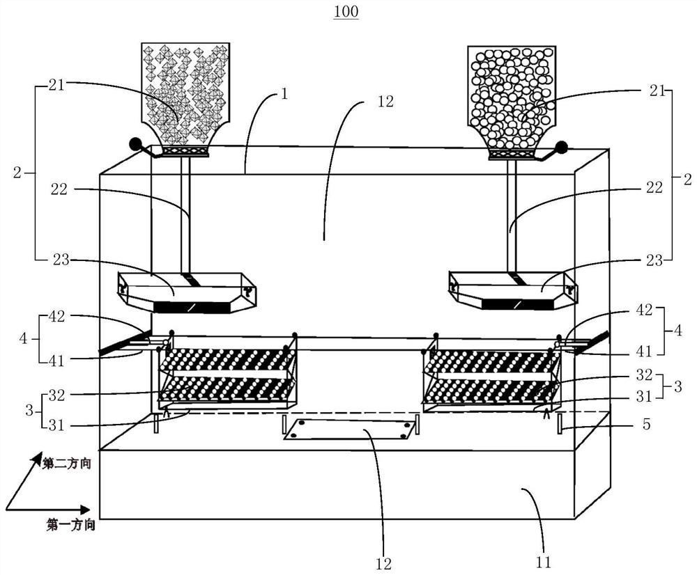
[0066] The directional powder feeding device 100 of the present invention specifically includes the following working steps:

[0067] 1) Load the dry CoCrMo alloy powder into the first powder feeding cylinder 21, and connect the first powder feeding cylinder 21 with the first powder cavity 23 to be laid through the first powder feeding conduit 22;

[0068] 2) The dry diamond powder is loaded into the second powder feeding cylinder 21, and the second powder feeding cylinder 21 is communicated with the second powder cavity 23 to be laid through the second powder feeding conduit 22;

[0069...

Embodiment 2

[0086] Example 2: NiTi alloy is widely used in aerospace and other fields due to its shape memory effect. Generally, NiTi alloy functional parts are formed by laser selective melting technology. Strain shrinkage occurs and the internal stress increases, and the NiTi crystal type cannot meet the phase transformation requirements. Shortening the waiting time of continuous processing is an important means to ensure the good crystal form of functional parts of NiTi alloy. The automatic control fine and orderly directional powder feeding system 2 proposed by the present invention can realize rapid powder feeding.

[0087] In this embodiment, the metal powder used is NiTi alloy, the sphericity of the alloy powder is greater than 99%, and the particle size of the used powder is 42um. The directional powder feeding device 100 to install the system powder feeding device specifically includes the following steps:

[0088] 1) The dry NiTi alloy powder is loaded into the first powder fee...


PUM

PropertyMeasurementUnit
widthaaaaaaaaaa
Rockwell hardnessaaaaaaaaaa

Abstract

The invention provides a directional powder feeding device and selective laser melting forming equipment. The directional powder feeding device comprises a forming chamber, at least two powder feeding systems, at least two powder spreading systems and a driving device. The forming chamber comprises a base and a forming cavity, and a substrate is arranged on the base; each powder feeding system comprises a powder feeding cylinder arranged above the forming chamber, a guide pipe and a to-be-laid powder cavity arranged in the forming cavity, the powder feeding cylinder is communicated with the to-be-laid powder cavity through the guide pipe, and a powder outlet is formed in the bottom of the to-be-laid powder cavity; the powder spreading system is movably arranged below the powder feeding system; and the driving device is connected with the powder spreading system. After to-be-processed powder enters the to-be-paved powder cavity from the powder feeding cylinder through the guide pipe, the to-be-processed powder falls into the powder paving system through the powder outlet, the powder paving system moves below the to-be-paved powder cavity, so that the to-be-processed powder is uniformly paved in the powder paving system, and all the powder paving systems are sequentially transferred to the base plate to be overlapped layer by layer; and it is guaranteed that the powder to be laid in the two powder feeding cylinders is directionally and evenly arranged on the base plate.

Description

technical field [0001] The invention relates to the technical field of additive manufacturing, in particular to a directional powder feeding device and a laser selective melting and forming equipment. Background technique [0002] With the increase of drilling depth, rock formations with high hardness and strong abrasiveness are often encountered. Diamond is the hardest substance that has been proved in nature, with a Rockwell hardness of 10, high wear resistance, high heat High conductivity and strong deformation resistance, these excellent physical and mechanical properties make it an important raw material for the manufacture of superhard drilling tools. There are various manufacturing methods for diamond tools. Traditional manufacturing methods generally include sintering method, electroplating method, welding method, etc. These manufacturing methods have their own advantages and disadvantages, but they are not suitable for diamond tool processing with high precision, co...

Claims


Application Information

Patent Timeline
Patent Type & Authority Applications(China)
IPC IPC(8): B22F12/50B22F12/55B22F12/00B22F10/28B22F10/37B33Y10/00B33Y30/00B33Y70/10B22F1/14B33Y70/00B22F5/00C22C26/00C22C1/04B22F12/70
CPCB22F12/50B22F12/55B22F12/00B22F10/28B22F10/37B33Y10/00B33Y30/00B33Y70/10B33Y70/00B22F5/00C22C26/00C22C1/0433B22F12/70B22F2005/001Y02P10/25
Inventor 周燕陶亚坤段隆臣
Owner CHINA UNIV OF GEOSCIENCES (WUHAN)
Why Eureka
Try Eureka