
Protection control circuit for power chip

A protection control and circuit technology, applied in the field of smart grid, can solve the problems of limiting device swiftness, complex hardware circuit, and high technical cost, and achieve the effects of ensuring swiftness, simple circuit structure, and low technical cost.

Pending Publication Date: 2022-06-24
GUIZHOU POWER GRID CO LTD +1
View PDF0 Cites 0 Cited by
  • Summary
  • Abstract
  • Description
  • Claims
  • Application Information

AI Technical Summary

Problems solved by technology

[0004] The technical problem to be solved by the present invention: provide a protection control circuit for power chips to solve technical problems such as the protection control circuit in the prior art limits the quickness of the device, high technical cost and complex hardware circuit

Method used


Image

  • Protection control circuit for power chip
  • Protection control circuit for power chip
  • Protection control circuit for power chip

Examples


Embodiment Construction

[0035] The principles and features of the present invention will be described below with reference to the accompanying drawings. The examples are only used to explain the present invention, but not to limit the scope of the present invention.

[0036] The present invention will be described below with reference to the accompanying drawings.

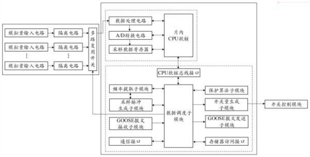
[0037] example, such as figure 1 As shown, a protection control circuit for a power chip includes a printed circuit board, a data sampling module, an FPGA module and a switch control module respectively integrated on the printed circuit board, and the FPGA module is embedded with an on-chip software a core CPU module, the FPGA module is respectively electrically connected with the on-chip soft-core CPU module, the data sampling module and the switch control module, and the data sampling module is electrically connected with the on-chip soft-core CPU module;

[0038] The data sampling module is used to collect multi-channel analog signals...


PUM


Abstract

The invention discloses a protection control circuit for a power chip, which comprises a printed circuit board, and a data sampling module, an FPGA module and a switch control module which are integrated on the printed circuit board, an on-chip soft core CPU module is embedded in the FPGA module, the FPGA module is electrically connected with the on-chip soft core CPU module, the data sampling module and the switch control module, and the on-chip soft core CPU module is electrically connected with the on-chip soft core CPU module. The data sampling module is electrically connected with the on-chip soft core CPU module; the data sampling module is used for collecting analog quantity signals; the on-chip soft core CPU module is used for respectively processing the analog quantity signals to obtain switching value input signals; the FPGA module is used for performing parallel logic operation according to the switching value input signal to generate a switching control signal; the switch control module is used for operating according to the switch control signal to complete protection control; the technical problems that a protection control circuit in the prior art limits the quickness of a device, the technical cost is high, and a hardware circuit is complex are solved.

Description

technical field [0001] The invention belongs to the technical field of the smart grid field, and in particular relates to a protection control circuit for a power chip. Background technique [0002] The smart grid digital substation incorporates all functions such as protection and safety automatic devices in the original substation into the substation automation system. The protection control function is an important measure of substation automation. All primary equipment in the power system must be equipped with protection control. device. [0003] In the traditional protection control design scheme, the architecture of CPU / DSP+MCU is mostly used, which has certain flexibility and operability. However, this scheme is executed serially, and the bottom layer of the hardware is expressed as a small number of operation units. Time-division multiplexing, the speed and number of operation units limit the overall execution speed of the protection algorithm and the rapidity of th...

Claims


Application Information

Patent Timeline
Patent Type & Authority Applications(China)
IPC IPC(8): G05B19/042
CPCG05B19/0423G05B2219/24215
Inventor 徐长宝辛明勇金学军李鹏习伟高吉普王宇姚浩祝健杨何雨旻陈军健刘德宏张历冯起辉
Owner GUIZHOU POWER GRID CO LTD
Learn More