Optimization method of fixed layer in MTJ structure

An optimization method and fixed layer technology, which is applied in the field of memory, can solve the problem of increasing the thickness of the fixed layer, and achieve the effect of reducing the thickness and reducing the thickness without affecting the stability

Pending Publication Date: 2022-06-24
ZHEJIANG HIKSTOR TECHOGY CO LTD
View PDF0 Cites 0 Cited by
  • Summary
  • Abstract
  • Description
  • Claims
  • Application Information

AI Technical Summary

Problems solved by technology

[0005] On the one hand, the demand for high PMA leads to an increase in the thickness of the fixed layer;
[0006] On the other hand, the total bias field of the fixed layer at the free layer needs to be controlled within a reasonable range, and the thickness of some magnetic layers in the fixed layer increases, resulting in an increase in the thickness of the fixed layer

Method used


Image

  • Optimization method of fixed layer in MTJ structure

Examples


preparation example Construction

[0048] The present invention has no particular limitations on the preparation methods of the above-mentioned layers, and the technical solutions of the preparation methods for forming the above-mentioned layer structures well known to those skilled in the art can be adopted.

[0049] The optimization method of the fixed layer in the MTJ structure provided by the present invention comprises the following steps:

[0050] a) reducing the thickness of the first pinning layer PL1, and increasing the magnetic moment of the first pinning layer PL1;

[0051] b) reducing the magnetic moment of the second pinning layer PL2, and reducing the thickness of the second pinning layer PL2;

[0052] c) Decrease the thickness of the reference layer RL and decrease the magnetic moment of the reference layer RL.

[0053] In the present invention, preferably also includes:

[0054] Optimize the structure adjustment layer TL.

[0055] The present invention first reduces the thickness of the first...

Embodiment 1

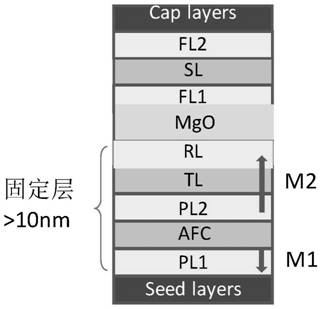
[0086] see figure 1 As shown, the following structures are formed in turn to realize the optimization of the fixed layer in the MTJ structure; the characteristics of each layer structure are:

[0087] (1) Small thickness first pinning layer PL1: Reduce the thickness of Co and Pt in the (Co / Pt)n multilayer to each molecular layer, that is, the thickness of each layer of Co and Pt is in the about n is controlled between 4 and 8; PL1 uses a high Ms Co alloy, such as Co x Fe 1-x (x is between 0.1 and 0.4), CoFeNi, etc., that is, materials with high Ms and strong perpendicular magnetic anisotropy with Pt; at the same time, increase the thickness of the layer of Co in contact with the AFC.

[0088] (2) Antiferromagnetic coupling layer AFC: make PL1 and PL2 form strong antiferromagnetic coupling, typical materials are Ru, Ir, Cr; the thickness is between 0.3 and 1.0 nm, preferably around 0.45 nm.

[0089] (3) Second pinning layer PL2 with small thickness and low magnetic moment...


PUM

PropertyMeasurementUnit
thicknessaaaaaaaaaa
thicknessaaaaaaaaaa
thicknessaaaaaaaaaa

Abstract

The invention provides an optimization method of a fixed layer in an MTJ structure. The optimization method comprises the following steps: reducing the thickness of a magnetic layer of the fixed layer; the magnetic moment of each magnetic layer is adjusted such that the bias field of the fixed layer at the free layer conforms to a set value. Compared with the prior art, the optimization method of the fixed layer in the MTJ structure provided by the invention can reduce the thickness of the fixed layer on the basis of not influencing the overall stability of the MTJ structure, thereby reducing the etching damage of the MTJ. Experimental results show that on one hand, the optimization method of the fixed layer in the MTJ structure reduces MTJ etching damage, and meanwhile, the stability of the reference layer is not affected; and on the other hand, the thickness of the whole storage unit is reduced, so that the etching time is favorably reduced, and more choices of photoetching and hard mask (HM) are provided for expanding to a small size.

Description

technical field [0001] The present invention relates to the technical field of memory, and more particularly, to a method for optimizing a fixed layer in an MTJ structure. Background technique [0002] The mainstream MRAM fabrication process adopts a bottom pin MTJ structure, which brings about a problem that after the barrier layer (usually MgO) is etched, the reference layer needs to be etched, and the antiferromagnetic coupling ( SAF) pinning layer and seed layer. However, the barrier layer is exposed to high-energy etching ions for a long time, and the characteristics of MTJ, such as endurance, breakdown voltage (BDV), tunnel resistance (Rp) and storage layer magnetic properties (such as coercivity) are affected. force Hc), etc., causing great damage. Therefore, how to reduce the etching damage after the exposure of the barrier layer is the key to improve the performance of MTJ. [0003] A typical tunnel junction layered stack (MTJ stack) structure is figure 1 As sho...

Claims


Application Information

Patent Timeline
Patent Type & Authority Applications(China)
IPC IPC(8): H01L43/08H01L43/12
CPCH10N50/01H10N50/10
Inventor 韩谷昌王明杨晓蕾哀立波张恺烨刘波
Owner ZHEJIANG HIKSTOR TECHOGY CO LTD
Why Eureka
Try Eureka