Pneumatic vibration device with rotatable piston shaft

A pneumatic vibration, piston shaft technology, applied in the direction of the drive device, fluid using vibration, boring machine/drilling machine components, etc., can solve the problems of easy wear of friction pairs, difficult manufacturing, high material requirements, etc., to improve chip removal ability and reduce Effect of cutting resistance, cutting temperature, and surface quality improvement

Pending Publication Date: 2022-06-28
SHENZHEN SUPERLINE TECH
View PDF3 Cites 0 Cited by
  • Summary
  • Abstract
  • Description
  • Claims
  • Application Information

AI Technical Summary

Problems solved by technology

However, when this structure is working, mechanical friction will be generated between the eccentric shaft and the lever ring, which will cause the friction pair to wear easily, and the requirements for materials are high, which will bring difficulties to manufacturing

Method used


Image

  • Pneumatic vibration device with rotatable piston shaft
  • Pneumatic vibration device with rotatable piston shaft
  • Pneumatic vibration device with rotatable piston shaft

Examples


Embodiment 2

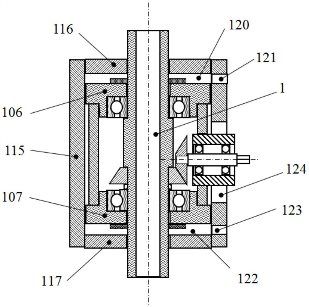
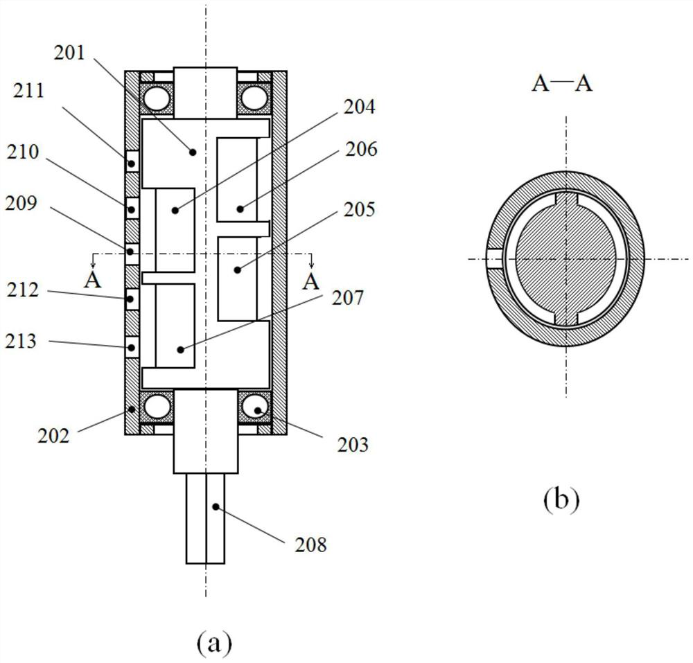
[0060] like Figure 7As shown, on the basis of Embodiment 1, there is no first exhaust groove 206 in this embodiment. In this way, when the mechanism is working, with the rotation of the ventilation shaft 201 of the gas commutator 2, the first exhaust groove 206 will The pressure in the piston chamber 120 is periodically increased without pressure relief, while the second piston chamber 122 is periodically pressurized and depressurized; such a design will result in a larger downward impact force when the piston shaft A1 vibrates, The upward impact is weaker.

[0061] Further, the gas commutator 2 may be electromagnetic, and its function is to supply the external pressure gas to the first piston cavity and the second piston cavity of the piston body alternately at a certain frequency. The structure of the electromagnetic gas commutator is not limited, and its exchange frequency can be adjusted.

Embodiment 3

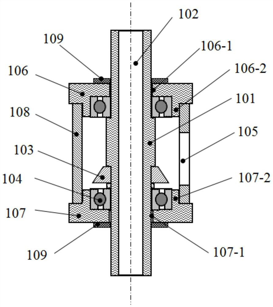
[0063] like Figure 8 As shown, on the basis of Embodiment 1, in this embodiment, the first piston 106 and the second piston 107 may also include a diaphragm structure, for example, an annular groove 106-3 is opened on the side of the first piston 106, An elastic diaphragm 106-4 is embedded in the annular groove 106-3, and the elastic diaphragm 106-4 has the function of supporting and sealing. When the piston shaft A1 vibrates, the elastic diaphragm 106-4 can deform. The same is true for the second piston 107 .

[0064] Such a design is effective for vibrations with small amplitudes, and at the same time, the machining difficulty of the piston is greatly reduced. Further, the elastic diaphragm 106-4 may be made of polymer material or metal material, and its structure and installation method are not limited.


PUM


Abstract

The invention provides a pneumatic vibration device with a rotatable piston shaft. The pneumatic vibration device comprises a piston body and a gas reverser. The piston body comprises a piston shaft, an input shaft and a piston cylinder, the piston shaft comprises a hollow main shaft, the two ends of the main shaft are connected with a first piston and a second piston through connecting bearings respectively, the first piston and the second piston are connected through an inner sleeve, and the main shaft is connected with a rotary connecting component; the input shaft extends into the inner sleeve and is connected with the rotary connecting component in a matched mode. A first piston cavity and a second piston cavity are formed between the side wall of the first piston and the piston barrel and between the side wall of the second piston and the piston barrel respectively. The first piston cavity and the second piston cavity are connected with the first air hole and the second air hole respectively. The gas reverser comprises a first gas exchange port and a second gas exchange port, and the first gas exchange port and the second gas exchange port are communicated with the first gas hole and the second gas hole respectively. By the adoption of the technical scheme, the structure is compact, adaptability is high, and rotation and vibration of the drilling tool are achieved.

Description

technical field [0001] The invention relates to a vibration device, in particular to a pneumatic vibration device with a rotatable piston shaft. Background technique [0002] When performing fine and deep hole drilling, if a small axial vibration is applied to the drilling tool, discontinuous cutting can be achieved, which is conducive to the discharge of chips, significantly reduces the cutting force, effectively prevents the tool from breaking, and improves the inner surface of the hole. quality. At present, there is a lot of technical information about the processing device of vibration and rotation. For example, Chinese patent CN107104514A discloses the arrangement of the piezoelectric ceramic vibrator on the rotating shaft of the motor in the surrounding wireless power transmission system suitable for automatic tool change of ultrasonic machining center. The upper part rotates together with the rotary shaft, and supplies power to the transducer through the non-contact ...

Claims


Application Information

Patent Timeline
Patent Type & Authority Applications(China)
IPC IPC(8): B23B47/04B23Q11/00B06B1/18
CPCB23B47/00B23Q5/043B23Q11/0042B06B1/18
Inventor 王中周劲松
Owner SHENZHEN SUPERLINE TECH
Why Eureka
Try Eureka