Laser marking machine for relay processing

A laser marking machine and laser marking technology, used in metal processing, metal processing equipment, laser welding equipment, etc., can solve the problems of inability to control relays well, one machine cannot be used for two purposes, and the marking quality is reduced. , to achieve the effect of convenient and orderly feeding work, increase feeding efficiency, convenient and flexible operation

Active Publication Date: 2022-06-28
黄山思贝乔机器人自动化设备有限公司
View PDF11 Cites 0 Cited by
  • Summary
  • Abstract
  • Description
  • Claims
  • Application Information

AI Technical Summary

Problems solved by technology

[0003] However, at present, when marking small batches of relays, it is necessary to use a conveyor belt for automatic feeding. However, when the number of relays is small or the volume and appearance are not suitable for continuous transportation, it needs to be placed on the table for marking. The situation that one machine cannot be used for dual purposes, and the conveyor belt marking machine will also cause space occupation and inconvenient transportation due to the prominent position of the conveyor belt, and when the relay is unloading, it cannot control the position of the relay well. The position and spacing will also cause the marking quality to decrease

Method used


Image

  • Laser marking machine for relay processing
  • Laser marking machine for relay processing
  • Laser marking machine for relay processing

Examples


Embodiment Construction

[0033] In order to make it easy to understand the technical means, creation features, achieved goals and effects of the present invention, the present invention will be further described below with reference to the specific embodiments.

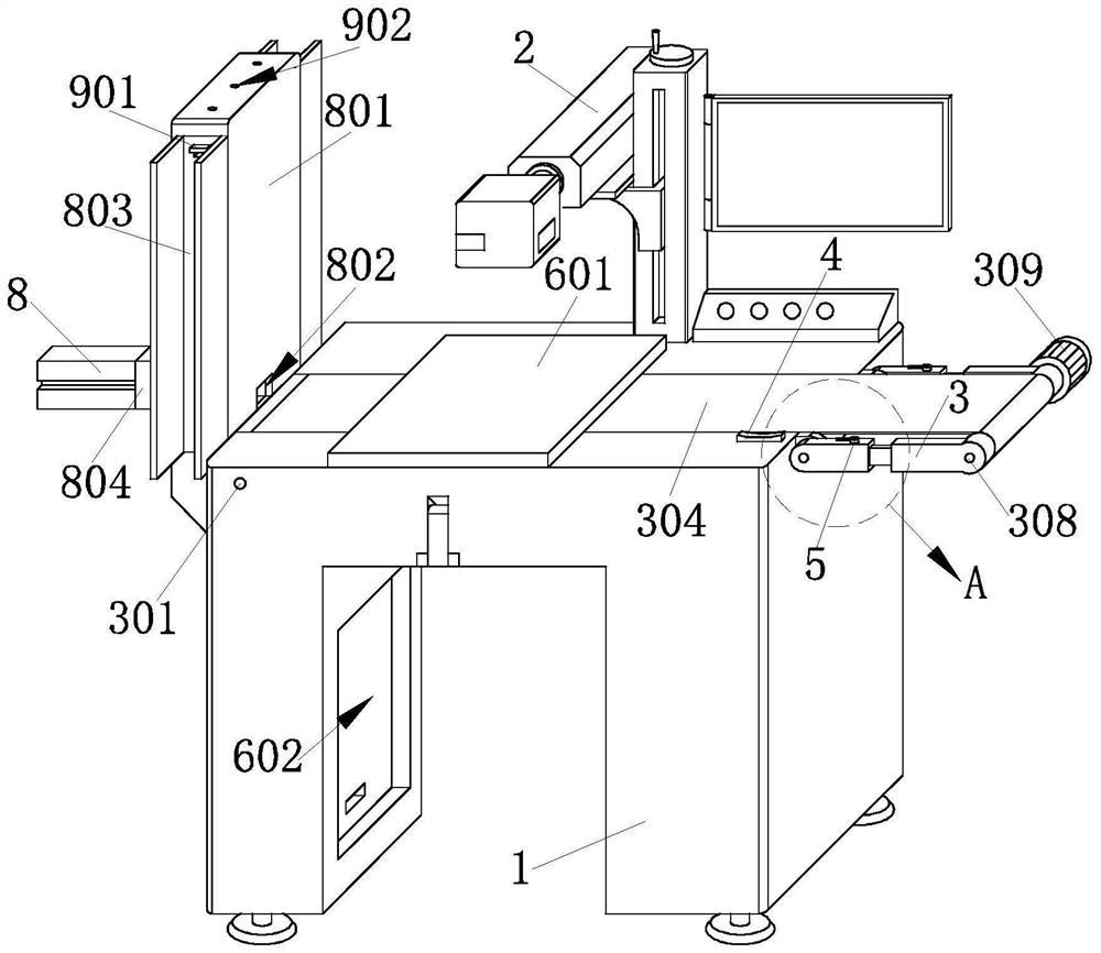
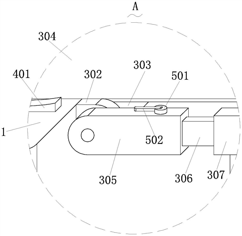
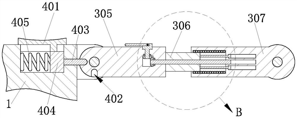
[0034] like Figure 1-Figure 9As shown, the laser marking machine for relay processing according to the present invention includes a workbench 1, a laser marking assembly 2 is installed on the workbench 1, a conveying structure 3 is installed on the workbench 1, The side end of the worktable 1 is provided with a fixing structure 4 , an adjustment structure 5 is installed on the conveying structure 3 , a mounting structure 6 is provided on the top of the worktable 1 , and is also installed on the worktable 1 There is a clamping structure 7, a feeding structure 8 is detachably installed on the side end of the worktable 1, and a positioning structure 9 is arranged on the feeding structure 8; the conveying structure 3 includes a first conveying r...


PUM


Abstract

The invention relates to the technical field of relay processing equipment, in particular to a laser marking machine for relay processing, which comprises a working table, a laser marking assembly mounted on the working table, a conveying structure mounted on the working table, a fixing structure arranged at the side end of the working table, and an adjusting structure mounted on the conveying structure. A mounting structure is arranged at the top end of the workbench, a clamping structure is further mounted on the workbench, a feeding structure is detachably mounted at the side end of the workbench, and a positioning structure is arranged on the feeding structure. Through the conveying structure arranged on the workbench, automatic and continuous feeding work can be conducted on the relays, the automatic conveying assembly can be folded and stored when continuous feeding operation is not needed, operation is convenient and flexible, and therefore the relay feeding device can meet different work requirements.

Description

technical field [0001] The invention relates to the technical field of relay processing equipment, in particular to a laser marking machine for relay processing. Background technique [0002] A relay is an electrical control device that is usually used in automated control circuits. It is actually an "automatic switch" that uses a small current to control the operation of a large current. Therefore, it plays the role of automatic adjustment, safety protection, and conversion circuit in the circuit. At present, in order to facilitate the installation of relays in the automatic control circuit, the laser marking machine is used to mark the model and circuit on the shell of the relay. [0003] However, at present, when marking small batches of relays, it is necessary to use conveyor belts for automatic feeding. However, when the number of relays is small or the volume appearance is not suitable for continuous conveying, it needs to be placed on the table for marking, which wil...

Claims


Application Information

Patent Timeline
Patent Type & Authority Applications(China)
IPC IPC(8): B23K26/362B23K26/70
CPCB23K26/362B23K26/702B23K2101/007Y02P70/10
Inventor 石群洁张正尧方成程田太平
Owner 黄山思贝乔机器人自动化设备有限公司
Why Eureka
Try Eureka