
Switching converter and control circuit thereof

A technology of switching converters and control circuits, applied in control/regulation systems, DC power input conversion to DC power output, instruments, etc., can solve problems such as poor load capacity, small loop bandwidth, slow response speed, etc., to achieve faster The effect of loop response speed, output ripple suppression, and system bandwidth improvement

Pending Publication Date: 2022-06-28
SG MICRO
View PDF0 Cites 0 Cited by
  • Summary
  • Abstract
  • Description
  • Claims
  • Application Information

AI Technical Summary

Problems solved by technology

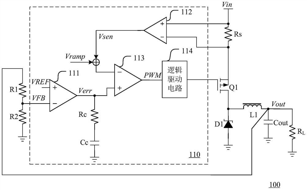
[0005] The switching converter 100 of the prior art has the disadvantages of small loop bandwidth, slow response speed, and poor load capacity, which cannot meet the needs of modern electronic systems with increasing performance.

Method used


Image

  • Switching converter and control circuit thereof
  • Switching converter and control circuit thereof
  • Switching converter and control circuit thereof

Examples


Embodiment Construction

[0022] Various embodiments of the present invention will be described in more detail below with reference to the accompanying drawings. In the various figures, the same elements are designated by the same or similar reference numerals. For the sake of clarity, various parts in the figures have not been drawn to scale.

[0023] It should be understood that in the following description, "circuitry" may include single or multiple combined hardware circuits, programmable circuits, state machine circuits, and / or elements capable of storing instructions executed by the programmable circuits. When an element or circuit is referred to as being "connected" to another element or an element / circuit is "connected" between two nodes, it may be directly coupled or connected to the other element or intervening elements may be present, and the connection between the elements may be be physical, logical, or a combination thereof. In contrast, when an element is referred to as being "directly...


PUM


Abstract

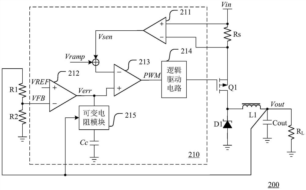
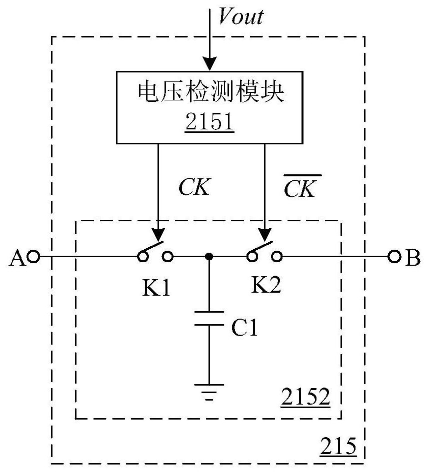
The invention discloses a switching converter and a control circuit thereof. The control circuit comprises a PWM comparator, a logic driving circuit and a compensation circuit. Wherein the compensation circuit comprises a variable resistance module and a compensation capacitor which are connected between the input end of the PWM comparator and the ground, the compensation circuit is used for performing frequency compensation on the error signal, and the variable resistance module is used for obtaining a clock signal with a preset frequency according to the direct-current output voltage and adaptively adjusting the resistance value of the variable resistance module according to the clock signal; therefore, dynamic frequency compensation can be carried out on the pole of the system to maintain the stability of the control system and suppress output ripples, the switching converter is kept stable in a large load range, the system bandwidth is greatly improved, and the loop response speed is increased.

Description

technical field [0001] The present invention relates to the technical field of power electronics, and more particularly, to a switching converter and a control circuit thereof. Background technique [0002] Switching converters have been widely used in portable computers, mobile phones, personal digital assistants, and other portable or non-portable electronic devices to generate operating voltages and currents required by internal circuit modules or loads. Switching converters use switching tubes to control the power transmission from the input end to the output end, so that a constant output voltage can be provided at the output end. [0003] figure 1 A schematic circuit diagram of a switching converter according to the prior art is shown. like figure 1 As shown, the switching converter includes a main circuit and a control circuit 110 . The main circuit includes a power switch tube Q1, a rectifier diode D1, an inductance Lx and an output capacitor Cout. The power swi...

Claims


Application Information

Patent Timeline
Patent Type & Authority Applications(China)
IPC IPC(8): H02M3/156H02M1/08H02M1/14
CPCH02M3/156H02M1/08H02M1/143
Inventor 肖飞
Owner SG MICRO
Learn More