Speed reduction device for slewing mechanism and method of speed reduction device

A technology of slewing mechanism and deceleration device, applied in the direction of transmission device, transmission device parts, gear transmission device, etc., which can solve the problems of increasing heat dissipation pressure of deceleration device, discounting vibration reduction effect, increasing energy consumption, etc., and widening the tuning frequency range Effect

Pending Publication Date: 2022-07-05
青岛海力达齿轮箱有限公司
View PDF6 Cites 1 Cited by
  • Summary
  • Abstract
  • Description
  • Claims
  • Application Information

AI Technical Summary

Problems solved by technology

Frictional damping is indeed a conventional idea for vibration reduction, but the existence of damping will inevitably increase the energy consumption of the entire system, and at the same time increase the heat dissipation pressure of the reduction gear
Although rubber vibration damping pads are widely used in construction machinery, the working environment of construction machinery is easy to cause rubber corrosion, which is also a pain point in the industry. If it is not replaced frequently or in time, the vibration reduction effect will be greatly reduced.
Both the damping spring and the scroll spring have the characteristics of positive stiffness. The vibration isolation effect of positive stiffness is far inferior to that of the latest researched negative stiffness vibration isolation system. The effect gap between positive stiffness and negative stiffness vibration isolation stability is obvious.

Method used


Image

  • Speed reduction device for slewing mechanism and method of speed reduction device
  • Speed reduction device for slewing mechanism and method of speed reduction device
  • Speed reduction device for slewing mechanism and method of speed reduction device

Examples


Embodiment Construction

[0032] The present invention will be further described in detail below with reference to the accompanying drawings, so that those skilled in the art can refer to the description and implement accordingly.

[0033] It should be understood that terms such as "having", "comprising" and "including" as used herein do not exclude the presence or addition of one or more other elements or combinations thereof.

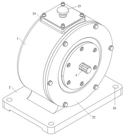
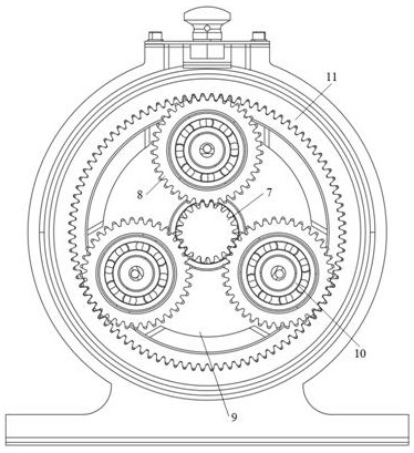
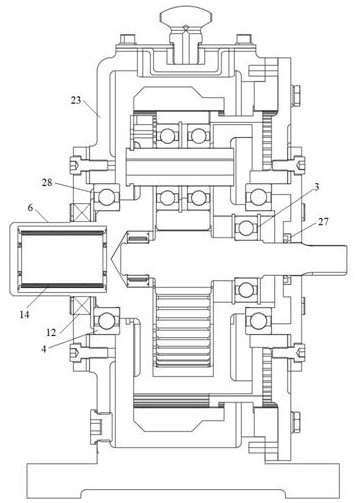
[0034] according to Figure 1-5 As shown, the present invention provides a reduction gear for a slewing mechanism and a method thereof, and the technical solutions are as follows:

[0035] A reduction gear for a rotary mechanism, comprising a reducer body 1 and a reducer base 2 fixed under the reducer body 1, a plurality of mounting holes 26 are provided around the reducer base 2, and the reducer base 2 passes through the mounting holes 26 is installed on the construction machinery, the reducer body 1 is a horizontal cylindrical structure, one end surface of the reducer body ...


PUM


Abstract

A speed reducer body is rotationally connected with an output shaft through an output bearing, the top end of an input shaft is meshed with a planetary gear through a sun gear, a planet carrier for installing the planetary gear is arranged at the top end of the output shaft, and the planetary gear is meshed with an inner gear ring fixed to the inner side of the speed reducer body. The output shaft and the speed reducer body are separated through a non-linear vibration reduction ring, the output shaft is provided with a tuning inerter vibration isolation unit through a concave groove, and the core design of the non-linear vibration reduction ring and the core design of the tuning inerter vibration isolation unit are both negative stiffness vibration isolation units. When vibration and impact exist in the negative stiffness vibration isolation unit, the positive curved spring leaf lobes deviate, the center lantern ring plays a role of a lever, the negative curved spring leaf lobes deviate in the opposite direction, extrusion exists between the positive curved spring leaf lobes and the adjacent negative curved spring leaf lobes, the moment length and the generalized stiffness of the negative stiffness vibration isolation unit are changed, and the negative stiffness vibration isolation unit is formed. And the vibration isolation and vibration reduction capabilities of the nonlinear vibration reduction ring and the tuning inerter vibration isolation unit are improved.

Description

technical field [0001] The invention relates to the technical field of construction machinery, in particular to a speed reduction device for a slewing mechanism and a method thereof. Background technique [0002] Construction machinery is an important part of the equipment industry, such as cranes and excavators. Most of the construction machinery works in the field, and its operation characteristics and requirements for the performance of the machinery have the following special features: (1) The quality of the project is a century-old plan, and the requirements for the quality of mechanical operations are getting higher and higher; (2) The working conditions of construction machinery are complex , The object of operation is changeable, and it often works under variable load conditions, which has higher requirements on the reliability and adaptability of the machine. Construction machinery is mainly composed of driving device, slewing mechanism, speed change device, transm...

Claims


Application Information

Patent Timeline
Patent Type & Authority Applications(China)
IPC IPC(8): F16H1/32F16H57/023F16H57/00F16H57/08F16H57/04F16F7/104F16F3/02
CPCF16H1/32F16H57/023F16H57/0006F16H57/0018F16H57/08F16H57/0434F16F7/104F16F3/023F16H2001/327F16H2057/0012F16F2228/063F16F2228/066F16F2228/04
Inventor 孙孔旭李静黄延明
Owner 青岛海力达齿轮箱有限公司
Why Eureka
Try Eureka